


26
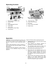
Cutterhead Removal
The entire cutterhead assembly may be removed
for cleaning or for bearing and blade replacement.
Some woodworkers keep a spare cutterhead with
replacement blades should the original cutterhead
have to be repaired.
Blades in the cutterhead are
sharp! Use extreme caution
when handling the removal of the cutterhead.
Failure to comply may cause serious injury!
To remove the cutterhead (including bearings,
studs, and housing) from the base casting:
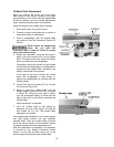
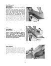
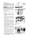
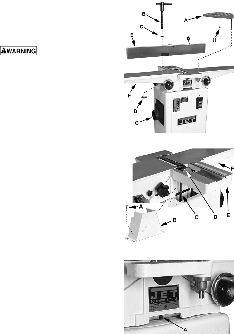
Referring to Figure 42:
1. Disconnect the machine from the power
source.
2. Remove the front blade guard (A) and
screw (H).
3. Remove the lock handle (B), washer (C) and
lock nut (D) securing the fence assembly (E) to
the table (F).
4. Lift the fence assembly (E) from the table.
5. From the left side of the stand, remove the
dust chute (G). From the back of the machine
remove the cabinet access cover (not shown).
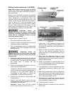
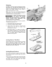
Referring to Figure 43:
6. Using an 8mm hex wrench, loosen two hex
cap screws underneath fence base casting (E)
that secure the casting to the table (F).
Remove the fence base casting and set aside.
7. Remove four screws and washers (A) securing
the belt guard (B). Remove the belt guard.
8. Remove the V-belt (C) from the cutterhead
pulley (D). If necessary, loosen the motor
mounting screws with a 12mm wrench to
provide slack on the V-belt.
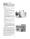
9. Using a 3mm hex wrench, loosen two set
screws that secure the cutterhead pulley (D) to
the cutterhead shaft. Set the pulley and shaft
key aside.
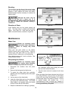
10. Using a 14mm wrench, remove two screws
(A, Fig. 44) and lock washers that secure the
cutterhead bearing housings to the base.
Note: These screws and lock washers are
more easily accessible through the dust chute.
11. Carefully remove the cutterhead (A, Fig. 45).
12. Before placing the new cutterhead back into
the casting, thoroughly clean the "saddle" and
the bearing housings of saw dust and grease
so that they seat properly.
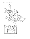
Figure 42
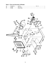
Figure 43
Figure 44