


8
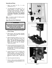
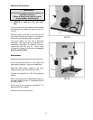
Adjusting90DegreeTableStop
1. Blade tension must be properly adjusted
prior to adjusting 90 degree stop, see
“Adjusting Blade Tension” page 13.
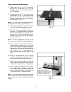
2. Loosen lock knobs (A, Fig. 7) and tilt table
until it rests against table stop bolt (B, Fig.
7). Tighten knobs.
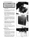
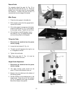
3. Use a square (E, Fig. 8) placed on the table
and against the blade to see if the table is
90 degrees to the blade.
4. If an adjustment is necessary, loosen the
lock knobs. Tilt the table until it is square to
the blade, and tighten the lock knobs.
5. Loosen lock nut (C, Fig. 7) and turn table
stop bolt (B, Fig. 7) until it contacts the
table. Tighten the nut (C, Fig. 7) to hold
table stop in place. When tightening the nut
hold the table stop bolt in place with a
wrench to prevent movement.
6. If necessary, adjust pointer (D, Fig. 7) to
zero.
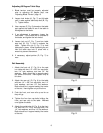
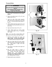
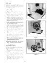
Rail Assembly
1. Attach the front rail (F, Fig. 9) to the cast
iron table with two 1/4” x 5/8” hex cap bolts,
two 1/4” lock washers, and two 1/4” flat
washers. Bolts should be in approximately
the center of the slot. Hand tighten only at
this time.
2. Attach the rear rail (G, Fig. 9) to the table
with two 1/4” x 5/8” hex cap bolts, two 1/4”
lock washers, and two 1/4” flat washers.
Bolts should be in approximately the center
of the slot. Hand tighten only at this time.
3. Push the front, and rear rails up as far as
they will go.
4. Tighten the four hex cap bolts holding the
front, and rear rails to the table. Do not
over tighten the bolts.
5. Attach the guide tube (H, Fig. 9) to the front
rail with five 1/4” x 5/8” hex cap bolts, five
1/4” lock washers, and five 1/4” flat washers.
Bolts should be in approximately the center
of the slot.