


9
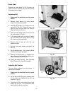
Fence Assembly and Adjustment
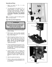
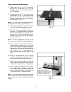
1. Attach the fence (A, Fig. 10) to the fence
body (B, Fig. 10) with four 5/16” x 3/4” hex
cap bolts, four 5/16” lock washers, and four
5/16” flat washers.
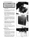
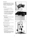
2. Thread a hex nut (D, Fig. 11) onto the pad’s
threaded stud (E, Fig. 11) and insert through
the fence and rear hook (F, Fig. 11).
Secure in place using a hex nut, lock washer
and flat washer (G, Fig. 11).
Note: The hook should be adjusted so that it
overlaps the rear rail by approximately 1/8”.
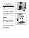
3. Place fence assembly onto the guide tube.
The rear hook should engage the rear rail.
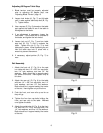
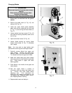
4. Check the clearance between the table and
the fence. The gap should be the same at
the front of the table as it is at the rear. If
the gap width is different, adjust the foot at
the rear of the fence until the gap width is
the same, Figure 12.
Note: You can also adjust the front rail, or rear
rail up, or down to achieve the proper clearance.
5. With a square verify the fence face is
perpendicular to the table top. If it is not the
front rail will need to be adjusted parallel to
the table top. This can be accomplished by
measuring from the top of the table to the
top of the front rail. The measurement
should be the same at both ends of the
table.
6. Move the fence assembly so that it aligns
parallel to the blade, and lock the fence by
pushing the lock handle down, Figure 10.
7. Loosen the four hex cap bolts that hold the
fence, to the fence body, and align the fence
to the blade. Tighten the four hex cap bolts.
8. Check to see that the pointer (C, Fig. 10) is
aligned with the zero marking on the guide
rail. If adjustment is necessary loosen the
screw that holds the pointer in place and line
up to the zero mark. Tighten the screw.
Note: If you cannot get the pointer lined up with
the zero mark you can slide the guide tube and
front rail left, or right to achieve the proper
setting.