


10
Assembly
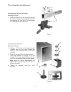
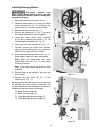
Handwheel
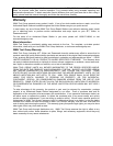
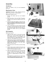
Attach the handle (A, Fig. 3) to the handwheel
(B, Fig. 3).
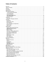
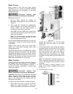
Mounting the Table
Important: The table is heavy. Mounting with the
help of another person is recommended.
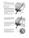
Referring to Figures 4 and 5:
1. Remove the table insert (A) and tapered
pin (B).
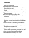
2. Slide the table so the saw blade (D) passes
through the slot where the tapered pin (B) was
located.
3. Rotate the table 90 degrees so that the miter
slot (C) is parallel to the blade (D) and to the
right of the blade when facing the band saw as
viewed in Figure 5.
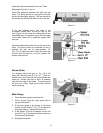
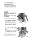
4. Line up the table (H) to the trunnions so that
the bolts (F) feed through the support bracket
(E). Secure the table with two lock knobs (G).
Reinstall the table insert (A) and tapered
pin (B).
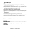
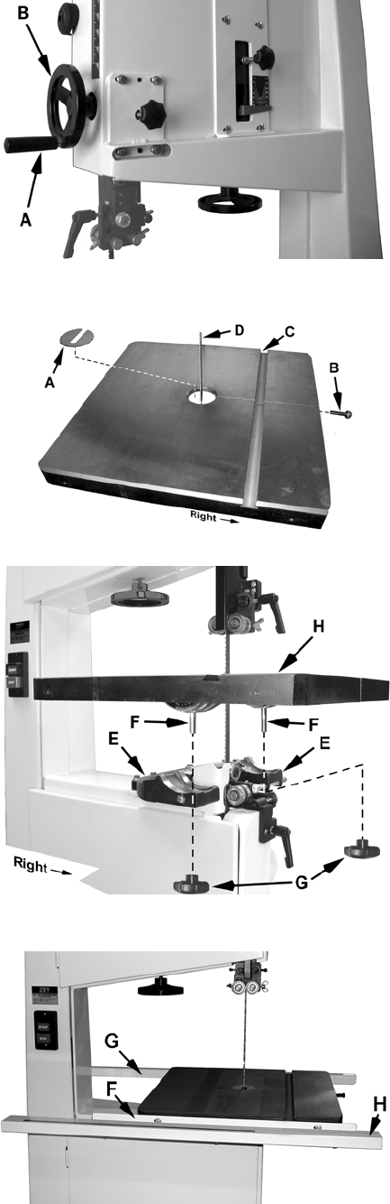
Rail Assembly
Referring to Figure 6:
1. Attach the front rail (F) to the cast iron table
with two 1/4” x 5/8” hex cap screws, two 1/4”
lock washers, and two 1/4” flat washers. The
screws should be in approximately the center
of the slot. Hand-tighten only at this time.
2. Attach the rear rail (G) to the table with two 1/4”
x 5/8” hex cap screws, two 1/4” lock washers,
and two 1/4” flat washers. Screws should be in
approximately the center of the slot. Hand-
tighten only at this time.
3. Push the front and rear rails up as far as they
will go.
4. Using a 10mm wrench, tighten the four hex cap
screws holding the front and rear rails to the
table. Do not over-tighten the screws.
5. Attach the guide tube (H) to the front rail with
five 1/4” x 5/8” hex cap screws, five 1/4” lock
washers, and five 1/4” flat washers. Screws
should be in approximately the center of the
slot.
Hand-tighten the guide tube only at this time.
You will be instructed to secure it later in the
Fence Assembly and Adjustment section.
Figure 3
Figure 4
Figure 5
Figure 6