


Stationary Electric Air Compressor Manual 9
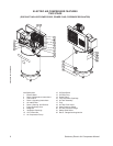
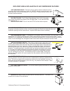
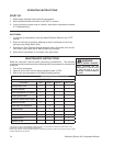
AIR TANK DRAIN VALVE: The drain valve is used to remove moisture from the
air tank(s) after the air compressor is shut off. NEVER attempt to open the drain valve
when more than 10 PSI of air pressure is in the air tank! To open the drain valve, turn
the knob counterclockwise.
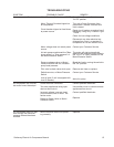
OIL SIGHT GLASS: The Oil Sight Glass displays the oil level in the pump.
The oil level should be at the center of the Oil Sight Glass. If low, add SAE 30W
non-detergent oil.
OIL FILL PORT/VENT: Pour oil into the Oil Fill Port/Vent when required.
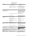
AIR INTAKE FILTER: This lter is designed to clean air coming into the pump. To ensure
the pump continually receives a clean, cool, dry air supply this lter must always be clean and
ventilation opening free from obstructions. Replace lter element when necessary.
AIR COMPRESSOR PUMP: To compress air, the pistons move up and down in the cylinders. On the
downstroke, air is drawn in through the air intake valves while the exhaust valves remain closed. On the
upstroke, air is compressed, the intake valves close and compressed air is forced out through the exhaust
valves, into the discharge line, through the check valve and/or the pilot valve and into the air tank.
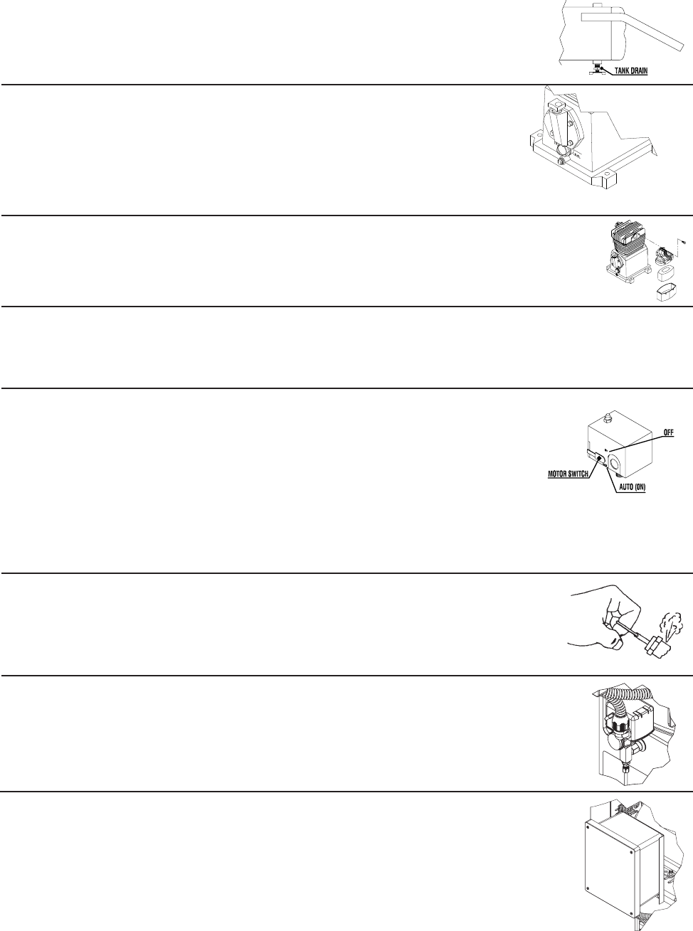
MOTOR/PRESSURE SWITCH: This switch is used to start or stop the air com-
pressor. Moving the switch to the "Auto" (On) position will provide automatic power
to the pressure switch which will allow the motor to start when the air tank pressure is
below the factory set "cut-in" pressure. When in the Start/Stop Option, the pressure
switch stops the motor when the air tank pressure reaches the factory set "cut-out"
pressure. For safety purposes, this switch also has a pressure release valve located
on the side of the switch designed to automatically release compressed air from the
air compressor pump head and its discharge line when the air compressor reaches
"cut-out" pressure or is shut off. This allows the motor to restart freely. Moving the
switch to the "Off" position will remove power from the pressure switch and stop the
air compressor.
SAFETY RELIEF VALVE: This valve is designed to prevent system failures by
relieving pressure from the system when the compressed air reaches a predetermined
level. The valve is preset by the manufacturer and must not be modied in any way. To
verify the valve is working properly, pull on the ring. Air pressure should escape. When
the ring is released, it will reseat.
AIR TANK PRESSURE GAUGE: The air tank pressure gauge indicates the reserve air
pressure in the air tank.
STARTER: the Motor starter provides thermal overload protection. The starter is re-
quired from on motors 5 Hp and above.
EXPLODED VIEW & EXPLANATION OF AIR COMPRESSOR FEATURES