Table Saw Operator's Manual 15
Assembly
ASSEMBLY PROCEDURES (CONT.):
7. Assembly of the Table Saw Stand and The Table Saw:
WARNING: DO NOT USE THIS TABLE SAW STAND WITH ANY
OTHER TOOL. DO NOT STAND ON TABLE SAW STAND OR USE
AS LADDER OR SCAFFOLDING. MAXIMUM LOAD: 300 LBS
(136KG). DO NUT USE TABLE SAW STAND IF IT IS DAMAGED
OR BENT.
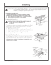
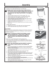
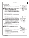
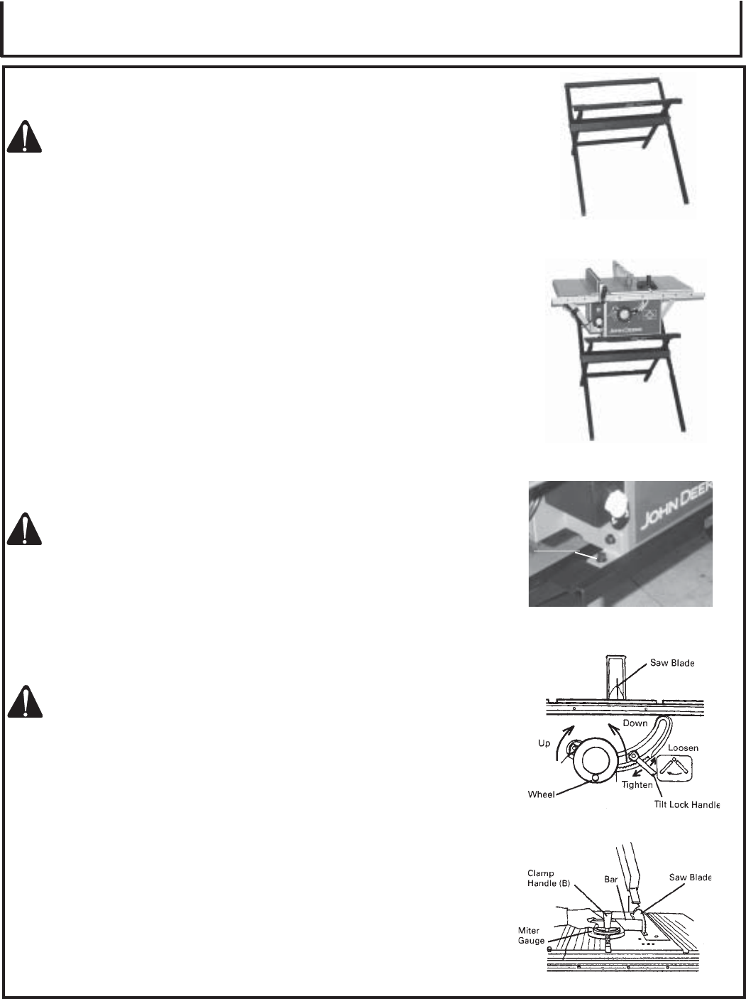
a. Unfold the table saw stand until it is fully opened. (Fig. 11-a)
b. Place the table saw stand upright on a solid flat level surface.
c. Place the table saw on the table saw stand. (Fig. 11-b)
d. Use the table saw stand and operate the table saw from the front
side (John Deere logo side) only. (Fig. 11-b)
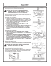
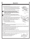
e. Fasten the table saw to the table saw stand with 8 x 20 mm bolts
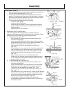
flanged nuts in all four corners. (Fig. 12)
f. Make sure the table saw is properly secured to the table saw stand
before use.
To close table saw stand:
a. Remove the four bolts, lift the table saw from table saw stand.
b. Pick the table saw stand up by the top rail and close it.
ADJUSTMENT:
This tool is accurately adjusted before shipping from the factory. Check the
following accuracies and readjust them if necessary in order to obtain the
best results in operation.
WARNING: TO AVOID AN ACCIDENT OR PERSONAL INJURY,
ALWAYS CONFIRM THAT THE SWITCH IS TURNED OFF
AND THE POWER PLUG HAS BEEN DISCONNECTED
FROM THE RECEPTACLE BEFORE ADJUSTMENT OF
THIS TOOL.
1. Adjustment of saw blade parallel to miter gauge groove:
This is the probably most difficult of the adjustments. Before shipment
from the factory, this adjustment was made but is should be rechecked
and readjusted if necessary.
CAUTION: THIS ADJUSTMENT MUST BE CORRECT. KICKBACK
COULD RESULT AND ACCURATE CUTS CANNOT BE
MADE.
a. Loosen the saw blade tilt lock handle by turning it counterclockwise.
Move the saw blade tilting mechanism to the left and set the saw
blade to 0° with the stopper.
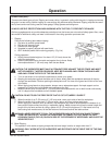
b. Turn the wheel fully clockwise and set the saw blade to the maximum
cutting height. (See 13-a)
c. Select a tooth on the saw blade which is bent to the right.
d. Mark the tooth with a pencil or permanent marker.
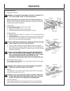
e. Set the miter gauge to 90° and tighten the clamp handle (B) to lock it
in that position. Place the miter gauge in the left hand miter gauge
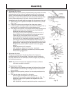
groove in the table top. (Fig. 13-b)
f. Rotate the saw blade to bring the marked tooth in the front and about
1/2" (12.7 mm) above the table top.
g. Place the bar of square flat against the miter gauge.
h. Move the bar of square toward the saw blade until it just touches the
top of the marked saw blade tooth.
i. Without disturbing the bar clamped to the miter gauge, move the
miter gauge to the center of the saw blade.
(Fig. 11-a)
(Fig. 13-b)
(Fig. 11-b)
(Fig. 12)
(Fig. 13-a)
BOLT


