Table Saw Operator's Manual 19
Operation
PRACTICAL OPERATIONS:
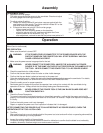
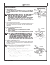
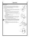
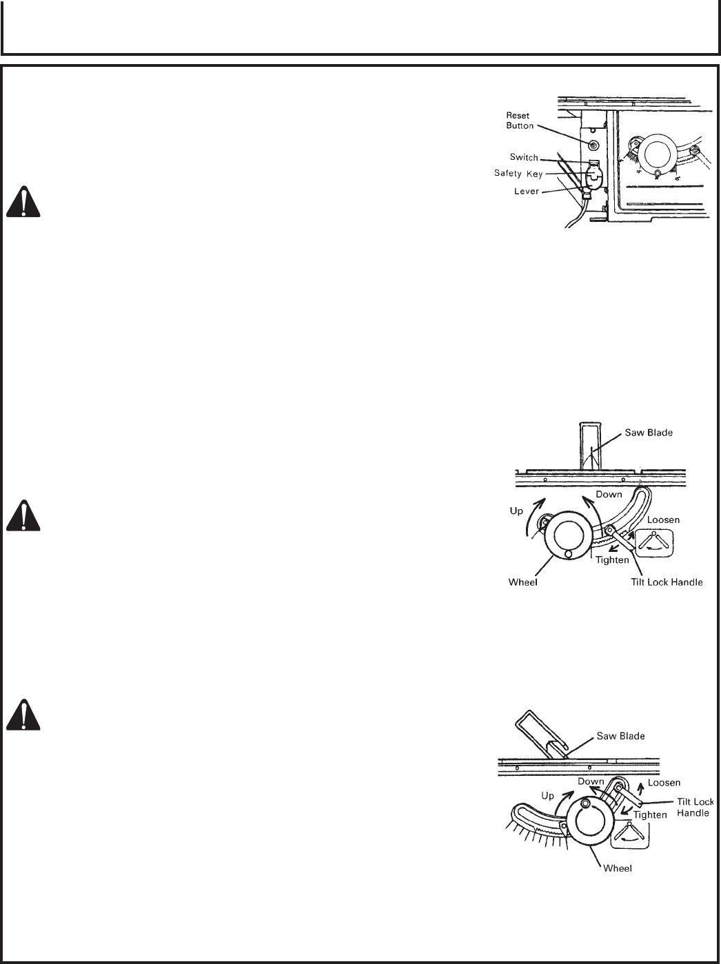
1. Switch Operations (Fig. 19):
To turn the table saw ON, lift the lever of the switch. To turn the table saw
OFF, push the lever of the switch. Try this operation without the saw being
plugged in.
WARNING: ALWAYS REMOVE THE SAFETY KEY FROM THE SWITCH
WHEN THE TABLE SAW IS NOT IN USE. THIS WILL ENSURE
THAT THE TABLE SAW CANNOT BE TURNED ON
ACCIDENTALLY OR BY SOMEONE (ESPECIALLY A CHILD) WHO
IS NOT QUALIFIED TO USE THE TABLE SAW. IF THE SAFETY
KEY IS LEFT IN THE SWITCH, SERIOUS PERSONAL INJURY CAN
RESULT.
2. Overload Protective Device for Motor:
When the motor becomes overload, the overload protective device cuts off
the current to stop the motor. In this case, after a few minutes, push the
reset button.
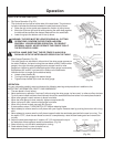
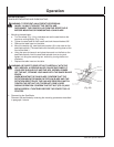
3. Raising and Lowering Saw Blade (Fig. 20):
a. Raising saw blade.
Grasp the wheel and rotate it clockwise to raise the saw blade.
b. Lowering saw blade.
Grasp the wheel and rotate it counterclockwise to lower the saw blade.
CAUTION: ADJUST THE SAW BLADE HEIGHT SO IT IS ABOUT 1/8"
(3.2 MM) ABOVE THE TOP OF THE WORKPIECE. RAISING
THE SAW BLADE MUCH HIGHER THAN THE WORKPIECE
DOES NOT MAKE IT CUT BETTER. IT IS UNSAFE AND
PROVIDES LESS TABLE SURFACE IN FRONT OF THE SAW
BLADE. NEVER OPERATE WHILE SAW BLADE IS ROTATING.
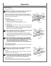
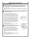
4. Saw Blade Tilting Operation (Fig. 21):
The saw blade tilt lock handle is spring loaded and can be repositioned by
pulling out on the handle and repositioning it on the serrated stud located
underneath the handle.
WARNING: THE SAW TILT LOCK HANDLE MUST BE LOCKED
DURING ALL CUTTING OPERATIONS.
To methods are available tilting saw blade and are as follows.
a. Rapid saw blade tilting.
Loosen saw blade tilt lock handle, move the wheel until the saw blade
is at the desired angle and tighten saw blade tilt lock handle.
b. Fine adjustment saw blade tilting;
- loosen saw blade tilt lock handle.
- push in wheel until teeth on hub of hand wheel engage with
segment gear.
- turn wheel to tilt the saw blade to the desired angle and tighten
saw blade tilt lock handle.
(Fig. 19)
(Fig. 20)
(Fig. 21)


