


14 Table Saw Operator's Manual
Assembly
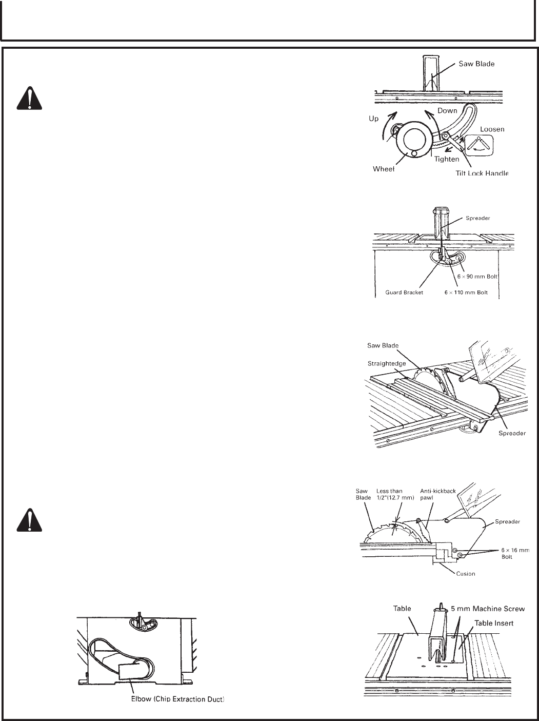
ASSEMBLY PROCEDURES (CONT.):
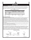
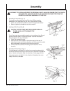
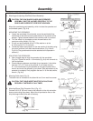
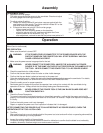
4. Mounting and adjusting Saw Blade Guard Assembly:
CAUTION: THE SAW BLADE GUARD AND SPREADER
ASSEMBLY MUST BE ALIGNED PROPERLY TO THE
SAW BLADE IN ORDER TO PREVENT KICKBACK.
Mount the saw blade guard assembly, which includes the spreader and
anti-kickback pawls. (Fig. 8-d)
MOUNTING THE SPREADER:
a. Loosen the saw blade tilt lock handle, move the saw blade tilting
mechanism to the left and set the saw blade to 0° by means of the
stopper. Tighten the saw blade tilt lock handle to lock it in position.
b. Turn the wheel fully clockwise and set the saw blade to the
maximum cutting height. (Fig. 8-a)
c. Put a 6 mm spring washer and a D13 flat washer on to the
6 x 90 mm and 6 x 110 mm bolts.
d. Tentatively fasten the spreader on the rear section of the body using
the cusion and two 6 mm bolts mentioned above. (Fig. 8-b and
Fig. 8-d) (The guard bracket must be attached to the spreader in
advance.)
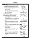
ADJUSTING THE SPREADER:
a. Use a straight edge to align the spreader with the saw blade.
(Fig. 8-c) Tighten the two 6 x 16 mm bolts (Fig. 8-d) with a wrench to
lock the spreader.
b. Check clearance between saw blade tip and spreader. It should be
less than 1/2" (12.7 mm) at all positions. If not, loosen the two
6 x 16 mm bolts securing the spreader to the guard bracket with a
wrench and move the spreader up and down. After adjustment of the
spreader is complete, firmly retighten the two 6 x 16 mm bolts with a
wrench. (Fig. 8-d)
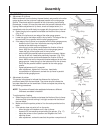
5. Mounting Table Insert (Fig. 9):
The table insert is mounted to the table with two 5 mm machine screws.
CAUTION: THE TABLE INSERT MUST BE IN PLACE AND
SECURELY FASTENED AT ALL TIMES.
6. Mounting Elbow (Chip Extraction Duct) (Fig. 10):
Connect a 2-9/16" (65 mm) hose to dust collector to the chip extraction
duct to suck cutting chips away. Mount the chip extraction duct on the
chip discharge outlet at the rear of the body.
(Fig. 8-a)
(Fig. 9)
(Fig. 8-b)
(Fig. 8-c)
(Fig. 8-d)
(Fig. 10)