


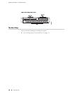

1. With one person standing on the left side of the chassis and another standing
on the right side, lift the unit into the rack.
2. Position the system in its designated location in the equipment rack. Make sure
the holes of the mounting brackets align evenly with the holes of the equipment
rack on both sides.
3. Starting at the bottom of the system, have the third person secure the system
in the equipment rack by using the 10-32 x 3/8 Phillips screws.
4. Connect the necessary cables.
Cabling the System
Cabling the system requires the following main tasks:
1. Familiarize yourself with the ports, and ensure that you have the cables and
wires needed to complete each cabling procedure.
2. Read and understand all safety warnings. (See “Installation Guidelines and
Requirements” on page 43.)
3. Connect the system to the network and to a management console.
4. Connect the other interfaces to their appropriate network interface.
5. Connect the power cables from the power source to the system's power supply.
NOTE: We recommend that you use shielded cables where appropriate.
See “System Specifications” on page 35 for more information about system
specifications.
Cabling the Management Console
Before powering up the system, you must set up a management console. The console
enables you to communicate with your system during the power-up process and to
manage your system using the command-line interface (CLI).
When connecting a console directly to the system, use a cable appropriate for your
terminal connector. The cable must have a female DB-9 connector to attach to the
RS-232 port on the system.
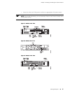
Management Ports
The management section of the system has three ports for management access (see
Figure 7 and Figure 9):
Cabling the System ■ 15
Chapter 3: Installing and Cabling the C-series Platform