


WWEELLDDIINNGG TTIIPPSS
• Make sure you move the torch across the weld at the proper speed. You want the
weld metal to flow smoothly onto the work piece. If the bead is too high or too wide,
your speed is too slow. If the bead is too narrow, your speed is too fast.
• If the flux-core wire is burning up before leaving the contact tip, the wire speed
is too slow. More tension should be added to the wire feed adjustment spring.
• If the flux-core wire is leaving the contact tip before being completely melted,
the wire speed is too fast. Less tension should be applied to the wire feed
adjustment spring.
• If the joint is not filled on the first pass, continue making passes until the weld-
ing joint is secure. Be sure to remove all remaining slag between passes.
•
NNeevveerr uussee aann eelleeccttrriicc aarrcc wweellddeerr ttoo tthhaaww ffrroozzeenn ppiippeess..
WWEELLDDIINNGG GGUUIIDDEELLIINNEESS
GGEENNEERRAALL
The KAWASAKI™ 90 Amp Wire Feed Welder incorporates a process called Flux
Cored Arc Welding (FCAW). The FCAW process uses a special tubular wire with flux
inside. When the current produced by the Welder flows through the circuit to the to
the welding wire, an electrical arc is created between the wire and the work piece.
Heat from the arc melts both the welding wire and the work piece. The liquefied
metal then flows into the molten crater on the work piece creating a welded bond.
AARRCC WWEELLDDIINNGG BBAASSIICCSS
There are five general basics that can affect the output of the welded work piece:
wire selection, heat setting, weld angle, wire speed, and travel speed.
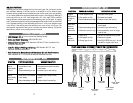
WWIIRREE SSEELLEECCTTIIOONN
The correct choice of welding wire can impact the effectiveness of the welding proj-
ect. Factors such as welding position, work piece material type, thickness, and sur-
face condition can affect the end results of the project. The American Welding
Society (AWS) has set guidelines for welding wire. An example is shown below.
EE--7700TT--GGSS
E- AWG classification for self-shielding wire
7 Weld Strength, times 10,000 lbs per square inch
0 Welding Positions: 0 = Flat, 1 = All other positions
T Tubular Flux-core Wire
-GS Flux Type
The Internet can be used for additional information on the American Welding
Society (AWS) Standards: http://www.aws.org/
16
HHEEAATT SSEETTTTIINNGG
Obtaining the correct heat setting involves adjusting the Welder to the required set-
ting. The proper heat setting is based on (1) diameter and type of welding wire, (2)
position of the weld, and (3) the thickness of the work piece. Labeling on the Welder
list recommendations for proper heat settings for most projects.
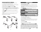
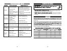
WWEELLDD AANNGGLLEE
The weld angle is the angle to which the torch head is held during the welding
process. The correct weld angle ensures proper heat penetration and bead forma-
tion. This becomes increasingly important in order to obtain a satisfactory weld.
Weld Angles involve two positions - travel angle and work angle. Travel Angle is the
angle in the line of welding that could vary from 5° to 45° from vertical, depending
on welding conditions. Work Angle is the angle from horizontal, measured in right
angles to the line of welding. Typically, a 45° travel angle and a 45° work angle is
sufficient. If special applications are needed, consult an arc welding handbook.
WWIIRREE SSPPEEEEDD
A knob on the front of the Arc Welder controls the wire speed. The speed needs to
be “tuned” to the proper rate at which the wire is being melted in the arc. Tuning is
one of the most critical functions in wire-feed welding. This procedure should be
performed on a scrap piece of metal that is the type and thickness as the work piece.
Using the scrap piece, begin welding by dragging the torch nozzle across the sur-
face with one hand while adjusting the speed with the other. If the speed is too slow,
sputtering will occur and the wire will burn up into the contact tip. If the speed is
too fast, sputtering will also occur but the wire will push into the plate before melt-
ing. A smooth “buzzing” sound indicates the wire speed is correctly tuned. Repeat
this procedure anytime the work piece changes or there is a change in heat setting
or wire diameter.
TTRRAAVVEELL SSPPEEEEDD
The travel speed is the rate at which the welding wire is moved across the work
piece. Factors such as type and diameter of the weld wire, amperage, position, and
work piece thickness all affect the travel speed necessary for a good weld. If the
speed is too fast, the bead becomes narrow and the bead ripples are pointed. When
the weld speed is too slow, the weld metal piles up and bead becomes high and
wide.
SSLLAAGG RREEMMOOVVAALL
After completing the welding project, wait for the metal pieces to cool before con-
tinuing. A protective coating called slag covers the weld bead preventing contami-
nants in the air from reacting with the molten metal. After the weld has cooled to
the point it is no longer glowing red, the slag can be removed. Use a chipping ham-
mer (this may be located on top of a wire brush handle) to break the slag away from
the weld. Final cleanup is done with the wire brush.