


Chapter 4: Front Panel
DN540
14 Operator Manual
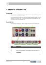
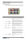
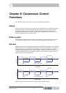
Compressor section
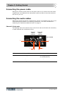
Each compressor section houses six compressor parameter control knobs, a bypass
switch and a hard knee switch, and two sets of six-LED meters (attenuation and level).
Item Type Label Function
1 Control knob ATTACK Adjusts the time taken for the compressor to respond
after an over threshold signal. (Envelope time
constant.)
2 Control knob GAIN Provides adjustment of up to 18dB of make up gain,
so that the level of the outgoing signal can be
matched to the incoming uncompressed signal.
3 Control knob RELEASE Adjusts the time taken for the compressor to recover
after an over threshold signal. (Envelope time
constant.)
4 Control knob PRESENCE Reduces compression at the mid-high frequencies
(vocal range), while allowing the low and high
frequencies to be compressed normally.
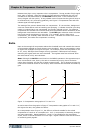
5 Pushbutton HARD Switches the compressor to hard knee. When this
button is switched off, the knee type is soft knee.
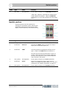
6LED
(orange)
Not applicable On/off status indicator for the HARD knee
pushbutton.
7 Control knob RATIO Controls the amount of compression applied to over
threshold signals.
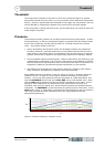
8LED meterATTEN Gain reduction meter. The compressor meter has
1dB, 2dB, 3dB, 6dB, 10dB and 20dB LEDs. No
additional time constants are applied to the meter, so
that the actual envelope speeds can be easily seen.
The gain reduction meter continues to function
normally when the DN540 is set in bypass. The
bypass indictors are illuminated boldly to signal this
fact to the user.
9 Control knob THRESHOLD Adjusts the operating point of the compressor.
10 Pushbutton BYPASS Removes the compressor/dynamic filter from the
signal path.
3
2
4
5
6
7
8
9
10
11
1
12