


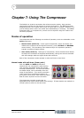

Modes of operation
DN540
Operator Manual 25
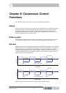
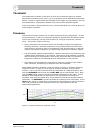
Figure 6: Compression - limiting signal level graphs
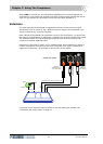
If a compression effect is required together with limiting of high level transients, two
channels of the DN540 may be cascaded. The output of Channel 1 (compression) is fed
to the input of Channel 2 (limiting), which gives powerful two stage control over gain.
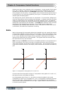
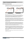
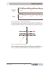
Figure 7: Limiting and compression graph
Below the compression threshold, the signal is unaltered. In the example shown in
Figure 7 “Limiting and compression graph”, the first threshold is compressed at a mild
2:1 ratio. Whereas, at the second threshold it is firmly limited at a ratio of 20:1.
Threshold level
Signal level
Limiting
Time
Unprocessed
Time
Signal level
signal
Threshold level
Input level (dB)
Output level (dB)
+20
+10
-10
-20
+10 +20-10-20
1:1
Compressor 2 threshold
Compressor 1 threshold