


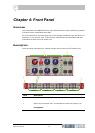
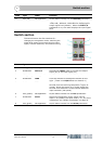

Switch section
DN540
Operator Manual 15
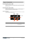
Switch section
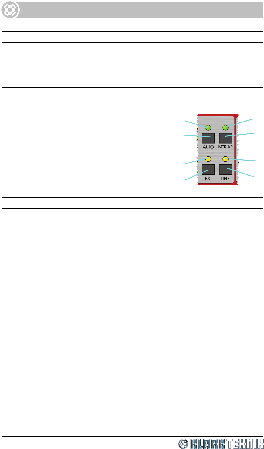
The switch section has four switches for:
changing the compressor mode; switching the
signal level meter from output signal to input
signal; external sidechain; and channel linking.
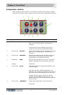
11 LED (red) Not applicable On/off status indicator for the BYPASS pushbutton.
12 LED meter LEVEL Signal level meter. The meter has +18dB, +12dB,
+6dB, 0dB, -6dB and -12dB LEDs for displaying the
output signal level (default). When the MTR I/P
pushbutton is on, the meter displays the input signal
level.
Item Type Label Function
1 LED (green) Not applicable On/off status indicator for the MTR I/P pushbutton.
2 Pushbutton MTR I/P Switches the LEVEL meter to monitor the output
signal (off) or the input signal (on).
3 LED (yellow) Not applicable On/off status indicator for the LINK pushbutton.
4 Pushbutton LINK Links the channel to the adjacent channel on the
right. (There is no LINK button on channel 4.)
5 Pushbutton EXT When this button is off, the sidechain signals are
sourced from the incoming compressor signal, as
normal. When this button is on, these signals are
sourced from elsewhere via the external sidechain
input connector (rear panel).
6 LED (yellow) Not applicable On/off status indicator for the EXT pushbutton.
7 Pushbutton AUTO Selects the compressor mode, where manual
mode = off (default) and auto mode = on. For more
information, see “Modes of operation” on page 23.
8 LED (green) Not applicable On/off status indicator for the AUTO pushbutton.
Item Type Label Function
1
2
3
7
8
5
6
4