


10
D.
When the correct adjustment is reached, lock the roller guides in
position with the guide adjusting screws.
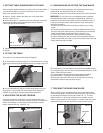
12. CHANGING THE BLADE SPEED
WARNING:
Before changing the speed always make sure the ma-
chine has been unplugged from the electrical supply.
This band saw has two blade speeds:
A.
1620 feet/min for hardwoods, some plastics and certain nonfer-
rous metals.
B.
3340 feet/min for all other timber.
The lower bandwheel has two, integral, multi-vee form pulleys and
the motor shaft has a twin multi-vee form pulley.
The drive belt passes around the bandwheel pulley, the motor pulley
and the tension wheel. The belt tension is released and applied by
using the crank handle
(See FIG. 22). This moves the tension wheel
and allows the speed to be changed.
(See DRIVE BELT POSITIONS HIGH/LOW SPEED on page 11)
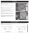
The Lower Blade Guide
A.
To adjust the lower blade guides, rst position the right and left
roller guides relative to the blade by loosening the lock nut (FIG. 21)
and moving the guide carrier until both roller guides are
approximately 1/16” behind the gullets (See Inset, FIG. 19) of the
saw blade.
B.
Set both roller guides to within 1/32” of the saw blade by releasing
the guide adjusting screw (FIG. 21) and moving the guide to desired
position. Lock the roller guide in position with the guide adjusting
screw. Do not set the roller guides too close as this will adversely
affect the life of the saw blade.
C.
Adjust the rear roller guide to be just clear of the back of the saw
blade by unlocking the guide adjusting screw (FIG. 21) and moving
the guide to approximately 1/32” behind the blade.
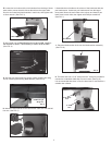
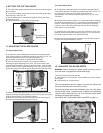
8. SETTING THE CUTTING HEIGHT
A.
The upper blade guide should be set as close as practical against
the work piece.
B.
To adjust this height, loosen the wing nut at the side of the upper
wheel housing. (See FIG. 18)
C.
Set the blade guide to the required height by turning the guide
post adjusting knob.
D.
Tighten the wing nut after setting proper height.
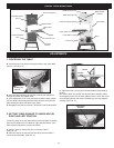
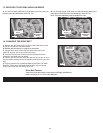
11. ADJUSTING THE BLADE GUIDES
The Upper Blade Guide
A.
To adjust the upper blade guides, rst position the right and left
roller guides relative to the blade by loosening the lock nut (FIG. 19)
and moving the guide carrier until both roller guides are
approximately 1/16” behind the gullets of the saw blade.
B.
Set both roller guides to within 1/32” of the saw blade by
releasing the guide adjusting screw (FIG. 19) on each side of the
saw blade and moving the guides to desired position. Lock the roller
guide in position with the guide adjusting screw. Do not set the roller
guides too close as this will adversely affect the life of the saw blade.
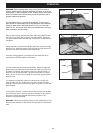
C.
Adjust the rear roller guide to be just clear of the back of the saw
blade by releasing the guide adjusting screw FIG. 20 and moving the
guide to approximately 1/32” behind the blade.
D.
When the correct adjustment is reached, lock the roller guide in
position with the guide adjusting screw FIG. 20.
Guide Post
Adjusting Knob
Wing Nut
FIG. 18
Guide Adjusting
Screw
Lock Nut
FIG. 19
FIG. 20
Guide Adjusting
Screw
FIG. 22
Crank Handle
Motor Pulley
Bandwheel pulley
FIG. 21
Lock Nut
Guide Adjusting
Screw
Tension Wheel
Blade Gullet
1/16”