


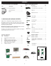
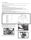
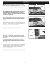

A. Open Stand Assembly
- Check contents against the parts list.
Hint:
All front and side panels assemble behind (inside) leg pieces.
- Fasten front panel on to paired legs, using hex carriage bolts, washers and hex nuts. Do not fully tighten.
- Fasten side panel on to front panel and paired leg assemblies using remaining hex carriage bolts, washers and hex nuts.
- Fasten the front and side beams on the paired legs with hex carriage bolts, washers and hex nuts.
- Set stand in an upright position, ensuring that the holes on the top edge of the panels line up sufciently to allow hex head screws to
pass through. Fully Tighten the hex carriage bolts and hex nuts.
- Press rubber feet onto the end of stand legs.
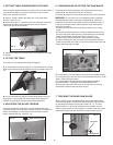
- With the aid of an assistant, lift band saw and carefully position in place on top of stand.
- Install base to stand using hex head screw (11) and washer (10) through stand and saw base, then washer (10) and hex nut (9) on top of
saw base. Repeat procedure for all four corners before tightening fully.
WARNING:
To Avoid back injury, get help lifting the band saw. Bend your knees, and lift with your legs, not your back.
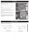
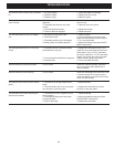
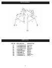
Parts List
Item No. Description Qty
1 Front beam 2
2 Side beam 2
3 Legs 4
4 Side panel 2
5 Front panel 2
6 Hex nut 24
7 Washer 24
8 Hex carriage bolt 24
9 Hex nut 8
10 Washer 8
11 Hex head screw 4
12 Rubber foot 4
13 Washer 4
3. INITIAL ASSEMBLY
The 10-321 band saw is supplied partly assembled. Prior to use, the following items have to be assembled: Open Stand, 2-1/2” Dust Port,
Table, Blade Tension Knob, Tool Holder, and Crank Handle.
WARNING:
To avoid injury, do not attempt to run or use this machine until all parts are assembled and working properly.
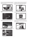
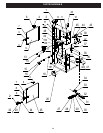
B.
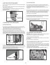
Assemble the 2-1/2” dust port to the band saw frame with Hex
socket head cap screw and washer. Place the 2-1/2” dust port onto
the side of the band saw frame.
Locate two Hex socket head cap screws and two washers from the
bag of loose parts. Mount the dust port to the band saw frame and
install a Hex socket head cap screw with washer in each hole, then
tighten with M5 Hex “L” wrench. (See FIG. 1)
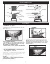
C.
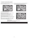
Assemble the upper table trunnion to the lower table trunnion with
Carriage Bolt, Glide Piece, Washer and Wing Nut (See FIG. 2).
D.
Place the table onto the upper table trunnion. Carefully feed the
blade through the slot of the table. (See FIG. 2A)
6
FIG. 2A
FIG. 2
Band Saw Open Stand
Parts Diagram
FIG. 1
Blade Slot
Carriage Bolt
& Glide Piece
Wing Nut &
Washer