


A-4
INSTALLATION
PRO-CUT 55
A-4
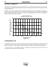
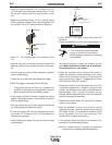
GAS INPUT CONNECTIONS
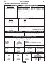
Supply the PRO-CUT 55 with clean compressed air or
nitrogen.
• Supply pressure must be between 80 psi
and 150 psi.
• Flow rate should be approximately 6.0
cfm (170 I/min.).
NOTE: Oil in the air supply to the PRO-CUT 55 can
cause severe problems. Use only a clean air
supply.
• Connect the gas supply to the PRO-CUT 55
regulator.
• Compressed gas should be supplied to the fit-
ting connection mounted on the filter at the
rear of the machine. If necessary, this fitting
can be removed allowing plumbing access
through the 1/4” NPT input port on the filter
body.
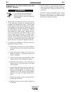
• If compressed air is being used, it is highly recom-
mended that an inline prefilter be installed in the air
supply line ahead of the air connection to the PRO-
CUT’s coalescing filter. While the coalescing filter is
used to remove small amounts of oil and water
aerosol particles from the air supply line, the prefilter
can be used to remove larger particulates before
they reach the coalescing filter element.This will pro-
long the life of the coalescing filter element by up to
six times what it would be without the prefilter, and in
turn, prolong the life of the PRO-CUT torch and con-
sumables as well.
• A standard nominal 5 micron inline prefilter is recom-
mended; however, for optimum performance, select
a prefilter with a 3 micron absolute rating. If these fil-
ter ratings are unavailable, anything with a rating
less than, or equal to, 20 micron would be accept-
able to use. In line filter elements will generally filter
the air with little restriction to the airflow until the ele-
ment is about 75 % contaminated. After this point,
there will be a noticeable pressure drop in the line.
Filter elements should be replaced when a pressure
drop of 8-10 psi is indicated; however, for optimum
performance of the PRO-CUT, the filter element
should be replaced at or before the pressure drop
reaches 8 psi. Be sure to select a prefilter that will
accommodate the necessary flow rating for the
PRO-CUT as specified in the Installation section of
this instruction manual under the Gas Input
Connections heading.
• While it is recommended that an in line prefilter be
placed ahead of each PRO-CUT that may be
installed in a shared air supply line, one large inline
prefilter may be used to accommodate several PRO-
CUTs simultaneously. If a shared prefilter is desired,
it must be rated to provide the necessary flow rate,
as specified, to ensure proper operation of each of
the PRO-CUTs sharing a connection.
NOTE: When using nitrogen gas from a cylinder, the
cylinder must have a pressure regulator.
• Maximum psi from nitrogen gas cylinder to
PRO-CUT 55 regulator should never
exceed 150 psi.
• Install a hose between the nitrogen gas
cylinder regulator and the PRO-CUT 55
gas inlet.
CYLINDER could explode if damaged.
• Keep cylinder upright and chained to a
fixed support.
• Keep cylinder away from areas where it
could be damaged.
• Never lift machine with cylinder attached.
• Never allow the cutting torch to touch the
cylinder.
• Keep cylinder away from live electrical
parts.
• Maximum inlet pressure 150 psi.
__________________
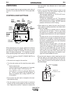
OUTPUT CONNECTIONS
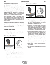
Torch Connection
The Pro-Cut 55 is sent from the factory with a PCT 80
cutting torch. Additional cutting torches can be
ordered from the K1571 series. Hand-held and mech-
anized torches come with 25' or 50’ cables.
All torches are connected to the Pro-Cut with a quick
connect at the bulkhead for easy change over. This
feature is excellent for changing between a hand cut-
ting torch and a mechanized torch. This feature is also
handy for troubleshooting.
For more information on the torch and its components,
refer to the PCT80 Operator’s Manual (IM588 latest
version).
WARNING