


A-8
INSTALLATION
RANGER 305G
A-8
CONNECTION OF LINCOLN ELECTRIC
WIRE FEEDERS
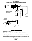
Connection of the LN-25 to the RANGER 305G
Shut off welder before making any electrical con-
nections.
------------------------------------------------------------------------
The LN-25 with or without an external contactor may
be used with the RANGER 305G. See the appropriate
connection diagram in Section F.
NOTE: The LN-25 (K431) Remote Control Module
and (K432) Remote Cable are not recommended for
use with the RANGER 305G.
1. Shut the welder off.
2. For electrode Positive, connect the electrode
cable from the LN-25 to the "+" terminal of the
welder and work cable to the "-" terminal of the
welder. For electrode Negative, connect the elec-
trode cable from the LN-25 to the "-" terminal of
the welder and work cable to the "+" terminal of
the welder.
3. Attach the single lead from the front of the LN-25
to work using the spring clip at the end of the lead.
This is a control lead to supply current to the wire
feeder motor; it does not carry welding current.
4. Set the MODE switch to the "CV-WIRE " position.
5. Set the "WELD TERMINALS" switch to "WELD
TERMINALS ON"
6. Set the "ARC CONTROL" knob to "0" initially and
adjust to suit.
7. Set the "IDLE" switch to the "AUTO" position.
When not welding, the RANGER 305G engine will
be at the low idle speed. If you are using an LN-25
with an internal contactor, the electrode is not
energized until the gun trigger is closed.
8. When the gun trigger is closed, the current sens-
ing circuit will cause the RANGER 305G engine to
go to the high idle speed, the wire will begin to
feed and the welding process started. When weld-
ing is stopped, the engine will revert to low idle
speed after approximately 12 seconds unless
welding is resumed.
If you are using an LN-25 without an internal con-
tactor, the electrode will be energized when the
Ranger 305G is started.
------------------------------------------------------------------------
Connection of LN-7 or LN-8 to the RANGER 305G
1. Shut the welder off.
2. Connect the LN-7 or LN-8 per instructions on the
appropriate connection diagram in Section F
3. Set the "WIRE FEEDER VOLTMETER" switch to
either "+" or "-" as required by the electrode being
used.
4. Set the "MODE" switch to the "CV WIRE " posi-
tion.
5. Set the "ARC CONTROL" knob to "0" initially and
adjust to suit.
6 Set the "WELD TERMINALS" switch to the
"REMOTELY CONTROLLED" position.
7. Set the "IDLE" switch to the "HIGH" position.
Connection of an LN-23P Wire Feeder to the
RANGER 305G
1. Shut the welder off.
2. Connect the LN-23P as per instructions on the
appropriate connection diagram in Section F.
(NOTE): When connecting an LN-23P to the
RANGER 305G, a K350-1 adapter kit must be
used.
3. Set the "VOLTMETER" switch to "-".
4. Set the "MODE" switch to "CV WIRE " position.
5. Set the "WELD TERMINALS" switch to
"REMOTELY CONTROLLED".
6. Set the "ARC CONTROL" knob to "0" initially and
adjust to suit.
7. Set the "IDLE" switch to the "AUTO" position.
When not welding, the RANGER 305G engine will
be at the low idle speed. If you are using an LN-
23P with the K350-1 adapter kit, the electrode is
not energized until the gun trigger is closed.
When the gun trigger is closed, the current sens-
ing circuit will cause the RANGER 305G engine to
go to the high idle speed, the wire will begin to
feed and the welding process can be started.
When welding is stopped, the engine will revert to
low idle speed after approximately 12 seconds
unless welding is resumed.
Connection of LN-742, Spool Gun, and Cobramatic
to RANGER 305G
1. Shut the welder off.
2. Connect per instructions on the appropriate con-
nection diagram in Section F.
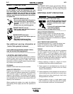
WARNING
CAUTION