


B-2
OPERATION
B-2
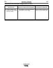
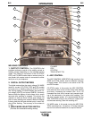
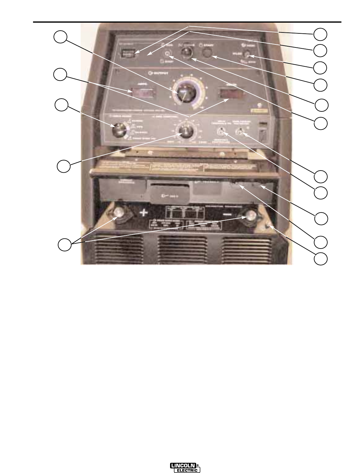
WELDING CONTROLS
1. OUTPUT CONTROL: The CONTROL dial
provides continuous control of the welding current or
welding voltage depending on the selected welding
mode. This control is not active in the CC-STICK,
PIPE, and CV-WIRE modes when a remote control or
wire feeder with remote control is connected to either
the 6 pin or 14 pin Amphenol.
2. DIGITAL OUTPUT METERS
The digital meters allow the output voltage (CV-WIRE
mode) or current (CC-STICK, PIPE and TIG modes)
to be set prior to welding using the OUTPUT control
dial. During welding, the meter display the actual out-
put voltage (VOLTS) and current (AMPS). A memory
feature holds the display of both meters on for seven
seconds after welding is stopped. This allows the
operator to read the actual current and voltage just
prior to when welding was ceased. While the display
is being held the left-most decimal point in each dis-
play will be flashing. The accuracy of the meters is
+/- 3%.
3. WELD MODE SELECTOR SWITCH:
(Provides four selectable welding modes)
CV-WIRE
PIPE
CC-STICK
TOUCH START TIG
4. ARC CONTROL :
The ARC CONTROL WIRE/STICK dial is active in the
WIRE and STICK modes, and has different functions
in these modes. This control is not active in the TIG
and PIPE modes.
CC-STICK mode: In this mode, the ARC CONTROL
knob sets the short circuit current during stick welding
(arc-force). Increasing the number from -10 to +10
increases the short circuit current and prevents stick-
ing of the electrode to the plate while welding. This
can also increase spatter. It is recommended that the
ARC CONTROL be set to the minimum number with-
out electrode sticking. Start with a setting at 0.
CV-WIRE mode: In this mode, turning the ARC CON-
TROL clockwise from –10 (soft) to +10 (crisp) changes
the arc from soft and washed-in to crisp and narrow.
RANGER 305G
1
10
7
4
9
5
8
11
12
13
6
15
14
16
2
3