


A-2
INSTALLATION
SPREADARC
A-2
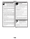
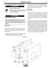
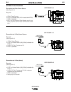
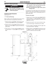
3. Remove the head mounting block from the NA-3,
NA-4, NA-5, or POWER FEED-10S head (if includ-
ed) by removing the four allen head cap screws.
This part is not used during the installation of the
Spreadarc. Mount the head to the Spreadarc using
the two 1/2-13 X 1.00 hex head screws, washers
and lock washers supplied with the Spreadarc
through the two large holes in the head mounting
pad.(See Figure A-2)
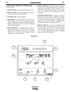
Note: Before mounting an NA-5 or PF-10S head to
the Spreadarc, in order to assure clearance between
the motor connection box and the Spreadarc head
mounting surface, the motor mounting to the gearbox
should be rotated per the instructions below:
1. Remove the four screws mounting the gearbox
assembly to the motor adapter plate, and remove
gearbox.
2. Remove the three screws mounting the adapter
plate to the motor, rotate the adapter plate 90°
clockwise and replace the three mounting screws.
3. Remount the gearbox assembly with the four
mounting screws.
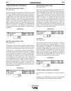
The drive motor is to be in the vertical position and the
drive rolls are to face the front. Loosen the head face
plate clamp screw and rotate the face plate so that the
idle roll arm is down. Install the nozzle, wire straight-
ener and flux hopper (if used) per the NA-3, NA-4,
NA-5, or PF-10S operating manual.
When using the K225 Twinarc nozzle, a K219 flux
hopper and a standard head mounting on a travel car-
riage, and when welding from left to right, a special
12" flux tube is required. The tube, which is included
with the Spreadarc, may be trimmed to length to fit the
installation. In addition, it is necessary to re-position
the steel plate on the nozzle to which the flux hose
retainer ring is attached. Remove the two screws
holding this plate and rotate the plate 180° so the ring
is closer to the bottom of the nozzle. Replace the
screws.
HIGH FREQUENCY PROTECTION
Locate the Spreadarc away from radio controlled
machinery. The normal operation of the Spreadarc
may adversely affect the operation of RF controlled
equipment, which may result in bodily injury or dam-
age to the equipment.
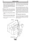
1/2-13 X 1.00
(2) HEX HEAD
SCREWS
SPREADARC SHOWN WITH
THE POWER FEED-10S WIRE DRIVE
FIGURE A-2