


B-1
OPERATION
B-1
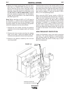
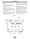
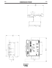
CASE FRONT CONTROL DESCRIPTION
(See Figure B-1)
1. ON/OFF SWITCH – Turns power on/off to the unit.
2. START BUTTON – Starts the oscillation based on
the values set in each of the modes.
3. STOP BUTTON – Stops oscillation.
4. JOG SWITCH – The Jog Switch will move the oscil-
lation carriage left or right at the speed set on the
Display. The speed can be pre-set before pressing
the Jog Switch left or right, or it can be changed
(real time) while jogging.
5. ADJUST SWITCH – The Adjust Switch is used to
change values stored in each mode. The Adjust
Switch can be used to set a value prior to starting
oscillation, or it can be used to change a mode
value (real time) while oscillating.
6. DIGITAL DISPLAY – Displays numerical settings
for each of the modes, such as Oscillation Speed in
inches per minute, Dwell Times in seconds, or Jog
Speed in inches per minute, under normal opera-
tion. Error codes are also displayed during fault
conditions.
7. LED MODE INDICATORS – Illuminate to show the
active mode. When a mode is selected, the Display
will show the current value. This value can be
changed using the Adjust Switch in a stopped con-
dition or during active oscillation. Modes can be
selected while actively oscillating (real time).
8. SELECT SWITCH – Used to select between the
available modes. When pressed up, the LED Mode
Indicators will scroll up the list. When pressed
down, the LED Mode Indicators will scroll down the
list. The Select Switch can be used in a stopped
state, or during active oscillation.
SPREADARC
1
23
5
6
7
8
4
FIGURE B-1