


B-4
OPERATION
B-4
WELDING PROCESS
For any electrodes the procedures should be kept within
the rating of the machine. For electrode information see
the appropriate Lincoln publication.
STICK (CONSTANT CURRENT) WELDING
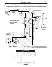
Connect welding cables to the "TO WORK” and "ELEC-
TRODE” studs. Start the engine. Set the "Polarity” switch
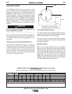
to the desired polarity. The “RANGE” switch markings
indicate the maximum current for that range as well as
the typical electrode size for that range. The “OUTPUT”
Control provides fine adjustment of the welding current
within the select range. For maximum output within a
selected range set the “OUTPUT” Control at 10. For min-
imum output within a selected range set the “OUTPUT”
Control at 5. (“OUTPUT” Control settings below 5 may
reduce arc stability) For best overall welding perfor-
mance set the “RANGE” Switch to the lowest setting and
the OUTPUT” Control near the maximum to achieve the
desired welding current.
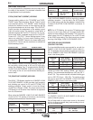
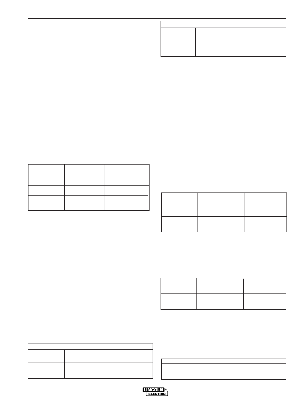
RANGE SETTING TYPICAL CURRENT RANGE
ELECTRODE SIZE
The RANGER 10,000 PLUS AND RANGER 10,000 can
be used with a broad range of AC and DC stick elec-
trodes. See “Welding Tips 1” included with the RANGER
10,000 PLUS AND RANGER 10,000 for electrodes with-
in the rating of this unit and recommended welding cur-
rents of each.
TIG (CONSTANT CURRENT) WELDING
The K930-[ ] TIG Module installed on a RANGER 10,000
PLUS AND RANGER 10,000 provides high frequency
and shielding gas control for AC and DC GTAW (TIG)
welding processes. Output control is from the Ranger
10,000 Plus & Ranger 10,000. The output control on the
TIG Module is not functional. After flow time is adjustable
from 0 to 55 seconds.
When using the RANGER 10,000 PLUS AND RANGER
10,000 for AC TIG welding of aluminum, the following
settings and electrodes are recommended:
The K930-[ ] TIG Module should be used with the RANGER
10,000 PLUS AND RANGER 10,000 on high idle to maintain
satisfactory operation. It can be used in the AUTO position
but the delay going to low idle after welding is ceased will be
increased if the AFTER FLOW CONTROL is set above 10
seconds.
NOTE: For AC TIG Welding, the maximum TIG welding output
currents on each range setting will be approximately 50%
higher than those marked on the nameplate. This is due to the
special nature of the AC TIG welding arc. Do not AC TIG weld
on the 225AC range setting. The output current may exceed
the rating of the Ranger 10,000 PLUS & RANGER 10,000.
WIRE FEED WELDING PROCESSES
(CONSTANT VOLTAGE)
The Innershield® electrode recommended for use with the
RANGER 10,000 PLUS AND RANGER 10,000 is NR
®
-211-
MP. The electrode sizes and welding ranges that can be used
with the RANGER 10,000 PLUS AND RANGER 10,000 are
shown in the following table:
The RANGER 10,000 PLUS AND RANGER 10,000 is recom-
mended for limited “MIG” welding (GMAW - gas metal arc
welding). The recommended electrodes are .030” and .035” L-
50 and L-56. They must be used with a blended shielding gas
such as C25 (75% Argon - 25% CO
2
). The welding ranges
that can be used with the RANGER 10,000 PLUS AND
RANGER 10,000 are shown in the following table:
ARC GOUGING
The RANGER 10,000 PLUS AND RANGER 10,000 can be
used for limited arc gouging.
Set the Range switch to adjust output current to the desired
level for the gouging electrode being used according to the rat-
ings in the following table:
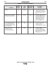
RANGER 10,000 PLUS AND RANGER 10,000
Diameter Wire Speed Approximate
(in.) Range In./Min. Current Range
.035 80 - 110 75A to 120A
.045 70 - 130 120A to 170A
.068 40 - 90 125A to 210A
Diameter Wire Speed Approximate
(in.) Range In./Min. Current Range
.030 75 - 300 50A to 130A
.035 100 - 250 90A to 175A
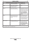
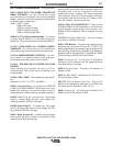
SETTINGS FOR PURE TUNGSTEN
TUNGSTEN RANGE SWITCH APPROXIMATE
DIAMETER (in.) SETTINGS CURRENT RANGE
1/8 90 or 145 80 - 150 Amps
3/32 90 or 145 45 - 130 Amps
1/16 90 40 - 80 Amps
SETTINGS FOR 1% THORIATED TUNGSTEN
TUNGSTEN RANGE SWITCH APPROXIMATE
DIAMETER (in.) SETTINGS CURRENT RANGE
1/8 90, 145, or 210 80 - 225 Amps
3/32 90 or 145 50 - 180 Amps
1/16 90 or 145 45 - 120 Amps
ELECTRODE SETTING CURRENT RANGE (DC, electrode positive)
1/8 30 - 60 Amps
5/32 90 - 150 Amps
3/16 150 - 250 Amps
90 MAX.
145 MAX.
210(DC)/225(AC)
MAX.
3/32
1/8
5/32
40 TO 90 AMPS
70 TO 145 AMPS
120 TO 210(DC),
225(AC) AMPS