


B-2
OPERATION
B-2
POWER MIG (140, 180 MODELS)
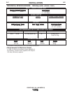
CONTROLS AND SETTINGS
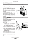
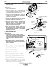
This machine has the following controls:
See Figure B.1
1. POWER SWITCH – Turns power on and off to the
machine.
2. ARC VOLTAGE CONTROL – This knob sets the
output voltage of the machine. Along with wire feed
speed (WFS) this control sets a weld procedure.
Refer to the procedure decal on the inside wire
drive compartment door to set a correct welding
procedure based on type of material and thickness
being welded.
3. WIRE FEED SPEED CONTROL (WFS) – The knob
sets the speed that the machine feeds wire. Along
with arc voltage this control sets a weld procedure.
Refer to the procedure decal on the inside wire
drive compartment door to set a correct welding
procedure based on type of material and thickness
being welded.
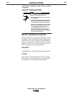
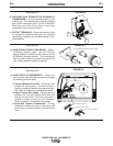
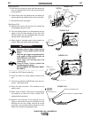
See Figure B.2
4. GUN TRIGGER – Depress the trigger to activates
the wire drive to feed wire and energizes the output
of the machine. Depress the trigger to weld and
release the trigger to stop welding.
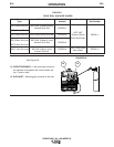
5. WELDING GUN – Delivers wire and welding cur-
rent to the weld.
a. Gun Liner – wire travels through the liner from
the wire drive. The gun liner will feed .025” to
.035” (0.6mm to 0.9mm) wire. The 180A machine
can weld with .045”(1.1mm) wire if an optional
.045”(1.1mm) liner is installed in the gun.
b. Contact Tip – provides electrical contact to the
wire.
c. Nozzle – When flux-cored welding the black noz-
zle protects the mounting threads on the gun.
When MIG welding the brass nozzle funnels the
shielding gas to the weld.
6. WORK CLAMP & CABLE – Clamps to the work
piece being welded and completes the electrical
welding circuit.
7. GUN TRIGGER CONNECTOR RECEPTACLE –
Plug the 4 pin gun trigger connector into this recep-
tacle.
1
3
2
FIGURE B.1
FIGURE B.2
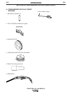
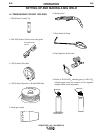
.035"(0.9mm)
NR-211-MP
WIRE SPOOL
4
5a
5b
5
5c
6
7