


B-10
OPERATION
B-10
POWER MIG (140, 180 MODELS)
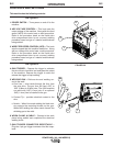
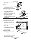
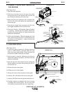
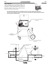
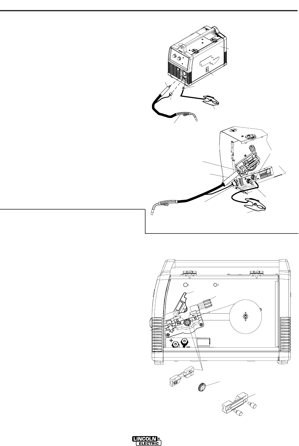
C. CONNECT LEADS AND CABLES ON
THE MACHINE
(See Figure B.14)
1. Open the case side door.
2. Slide the connector end of the gun and cable
through the hole of the machine front and into the
gun connector bushing on the wire drive.
3. Make sure the gun connector end is seated fully
into the wire drive and tighten the thumbscrew to
secure the gun.
4. Plug the gun trigger lead connector into the 4 pin
gun trigger receptacle on the machine front.
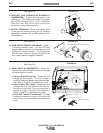
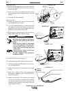
5. Wire Drive Polarity. MIG welding requires Positive
(+) polarity. Connect the short power cable from
the wire drive to the positive (+) output terminal and
tighten the thumbscrew.
6. Work Lead Connection. Slide the lugged end of the
work cable through the hole in the machine front
and place on the negative (-) output terminal and
tighten thumbscrew.
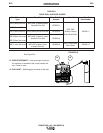
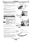
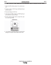
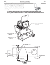
D. LOAD WIRE SPOOL
(See Figure B.15)
1. Locate the green labeled 4"(102mm) diameter
spool of .025”(0.6mm) L-56 solid MIG wire and
place onto wire spool spindle. Orient the spool so
that the wire feeds off the top of the spool.
2. Secure spool in place by tightening the wing nut
against the against the spacer that holds the wire
spool on the spindle.
3. Open the top drive roll pressure arm by rotating the
tension adjustor arm down and pivoting the idle roll
pressure arm up.
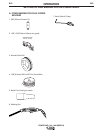
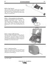
4. Remove the outer wire guide.
4a. Slide gun out of drive slightly.
5. Remove the lower drive roll and inner wire guide.
6. Install the .025”-.035”(0.6mm-0.9mm) inner wire guide.
7. Install the .025”(0.6mm) smooth grooved lower drive roll.
8. Carefully unwind and straighten the first six inches
of welding wire from the spool. Do not let the end
of the wire go to prevent the wire from unspooling.
GUN AND CABLE
WORK CLAMP
(4 PIN)
LEAD CONNECTOR
TERMINAL END
(FITS ON STUD INSIDE
SEE FIGURE BELOW)
SLIDE
CONNECTOR
END HERE
CASE SIDE DOOR
OPEN LATCH DOOR
WORK CLAMP
(4 PIN)
TRIGGER RECEPTACLE
PLUGGED IN
CONNECTOR
END ATTACH
ALL COMPONENTS SHOWN CONNECTED
(FRONT AND SIDE DOOR IS REMOVED
FOR CLARITY)
SHORT POWER
CABLE POSITIVE "+"
OUTPUT TERMINAL
WORK LEAD
CONNECTION
NEGATIVE "-"
OUTPUT TERMINAL
THUMB SCREW TO
TIGHTEN CONNECTOR
BUSHING
LOCATE COMPONENTS
TO CONNECT TO THE
FRONT OF MACHINE
FIGURE B.15
FIGURE B.14
WIRE SPOOL
.025" (0.6mm)
INNER WIRE GUIDE REMOVED
LOWER DRIVE ROLL REMOVED
OUTER WIRE
GUIDE REMOVED
TOP DRIVE ROLL PRESSURE ARM
TENSION ADJUSTOR DOWN
L
-
5
6
S
O
L
I
D
M
I
G