


B-11
OPERATION
B-11
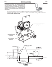
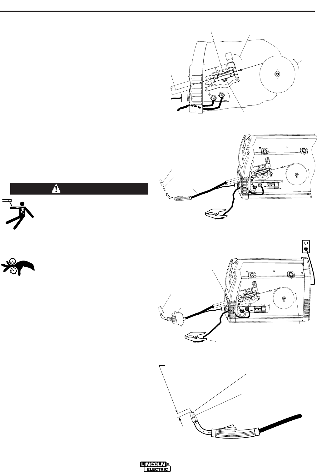
POWER MIG (140, 180 MODELS)
(See Figure B.16)
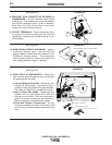
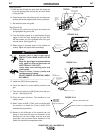
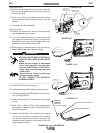
9. Feed the wire through the wire drive inlet along the
inner wire guide groove and into the wire drive out-
let on the gun side.
10. Close the top drive roll pressure arm and secure
by pivoting the tension adjustor back to the up
position.
11. Re-install the outer wire guide.
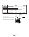
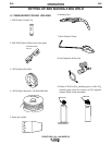
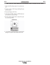
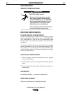
(See Figure B.17)
12. Remove the nozzle from the gun and contact tip
and straighten the gun out flat.
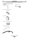
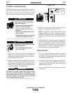
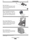
13. Turn the machine power to on and depress the
gun trigger to feed the wire through the gun liner
until the wire comes out of the threaded end of the
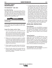
gun several inches. (See Figure B.18)
14. When trigger is released spool of wire should not
unwind. Adjust wire spool brake accordingly.
MOVING PARTS AND ELECTRICAL
CONTACT CAN CAUSE INJURY OR BE
FATAL.
•When the gun trigger is depressed
drive rolls, spool of wire and elec-
trode are ELECTRICALLY LIVE (HOT).
• Keep away from moving parts and
pinch points.
• Keep all Doors, Covers, panels and
guards securely in place.
DO NOT REMOVE OR CONCEAL
WARNING LABELS.
-----------------------------------------------------------------------
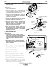
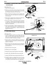
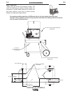
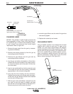
15. Install the .025”(0.6mm) contact tip.
16. Install the brass gas MIG welding nozzle to the gun.
17. Trim the wire stickout to 3/8”(9.5mm) from the nozzle
end. (See Figure B.19)
18. Close the case side door. The machine is now ready
to weld.
19. Read "Learn to Weld" (LTW1) that is included with
the machine or watch the "How to Weld" DVD includ-
ed with the machine.
20. Based on the thickness of the material you are going
to weld and the type and diameter of the welding
wire set the voltage and the wire feed speed per the
procedure decal attached to the inside of the wire
drive compartment door.
TENSION ADJUSTOR
LOCKED IN POSITION
DRIVE ROLL
BE SURE WIRE
IS IN GROOVE
WIRE SPOOL
.025" (0.6mm)
SLIDE WIRE
INTO GUN
CONNECTOR
SIDE
TOP IDLER ROLL
PRESSED AGAINST
LOWER DRIVE ROLL
DIRECTION
OF WIRE
L
-
5
6
S
O
L
I
D
M
I
G
REMOVED NOZZLE
REMOVED CONTACT TIP
LAY CABLE AND GUN STRAIGHTEN
IN THIS POSITION
WIRE SPOOL
.025" (0.6mm)
L
-
5
6
S
O
L
I
D
M
I
G
DEPRESS TRIGGER
TO ACTIVATE WIRE,
WHICH FEEDS THE WIRE
THRU THE LINER.
FEED WIRE
APPROXIMATELY 4.00"
FROM THE GUN TUBE END
ROTATION
PLUG IN POWER
INPUT CORD
ON/OFF
SWITCH
WORK CLAMP AND CABLE
WIRE SPOOL
.025" (0.6mm)
L
-
5
6
S
O
L
I
D
M
I
G
INSTALL .025 CONTACT TIP
INSTALL BRASS NOZZLE
TRIM WIRE
STICKOUT
3/8"(9.5mm)
from the Brass Nozzle
FIGURE B.17
FIGURE B.18
FIGURE B.19
FIGURE B.16
WARNING