


#()!!)$#
'#'Q
()#.%$,'$##)$#(
The RANGER® 225 is suitable for temporary, standby,
or emergency power using the engine manufacturer’s
recommended maintenance schedule.
The RANGER® 225 can be permanently installed as a
standby power unit for 240V-3 wire, single phase 38
ampere service.
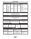
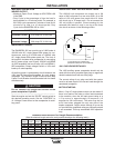
?>>53D9?>C=ECD25=1452I1<935>C545<53DB9
391>G8?31>45D5B=9>58?GD85+@?G5B
31>25141@D54D?D85@1BD93E<1B9>CD1<<1D9?>1>4
3?=@<IG9D81<<1@@<9312<55<53DB931<3?45C)85
6?<<?G9>79>6?B=1D9?>31>25EC541C17E9452I
D855<53DB9391>6?B=?CD1@@<931D9?>CB565B1<C?D?
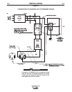
D853?>>53D9?>4917B1=C8?G>9>97EB5
1. Install a double pole, double throw switch between
the power company meter and the premises dis-
connect.
Switch rating must be the same or greater than the
customer’s premises disconnect and service over-
current protection.
2. Take necessary steps to assure load is limited to
the capacity of the RANGER® 225 by installing a
40 amp 240V double pole circuit breaker.
Maximum rated load for the 240V auxiliary is 38
amperes. Loading above 38 amperes will reduce
output voltage below the allowable -10% of rated
voltage which may damage appliances or other
motor-driven equipment.
3. Install a 50 amp 120/240V plug (NEMA type 14-50)
to the Double Pole Circuit Breaker using No. 8, 4
conductor cable of the desired length. (The 50 amp
120/240V plug is available in the optional plug kit.)
4. Plug this cable into the 50 amp 120/240V recepta-
cle on the RANGER® 225 case front.
,'##
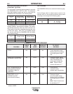
*-!'.%$,',!,!#
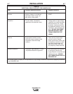
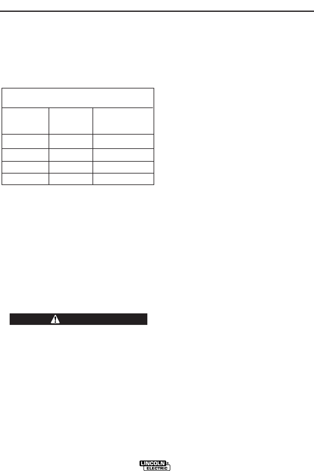
Simultaneous welding and power loads are permitted
by following Table I. The permissible currents shown
assume that current is being drawn from either the
120V or 240V supply (not both at the same time).
Also, the “Output Control” is set at “10” for maximum
auxiliary power.
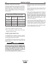
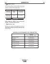
)!
("*!)#$*(,!##%$,'
$ED@ED(5<53D?B %5B=9CC92<5%?G5B %5B=9CC92<5EH9<91BI
(5DD9>7 ,1DDC*>9DI%?G5B EBB5>D9>=@5B5C
13D?B +
?B+
Max. Stick or Wire
Feed Setting None 00
145 Stick Setting 3450 32
** 16
90 Stick Setting 6000 50
** 25
No Welding 9000 76
** 38
Each duplex receptacle is limited to 20 amps.
Not to exceed 40A per 120VAC branch circuit when
splitting the 240 VAC output.