#()!!)$#
'#'Q-)
!$)$#+#)!)$#
The welder should be located to provide an unrestrict-
ed flow of clean, cool air to the cooling air inlets and to
avoid heated air coming out of the welder recirculating
back to the cooling air inlet. Also, locate the welder so
that engine exhaust fumes are properly vented to an
outside area.
() #
Ranger® 250 GXT machines cannot be stacked.
$##)$#$!#$!#!)'
,''(
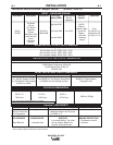
(8ED?66G5<45B256?B5=1;9>71>I5<53DB931<
3?>>53D9?>C
-----------------------------------------------------------------------
,'$#()#)+$!)
$##)$#$!#'$(()','
'
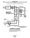
The LN-15 has an internal contactor and the electrode
is not energized until the gun trigger is closed. When
the gun trigger is closed the wire will begin to feed and
the welding process is started.
• Shut the welder off.
•
Connect the electrode cable from the LN-15 to
the
“ELECTRODE” terminal of the welder. Connect
the work cable to the “TO WORK” terminal of the
welder.
• Set the Polarity switch to the desired polarity, either
DC (-) or DC (+).
• Attach the single lead from the front of the LN-15
to work using the spring clip at the end of the lead.
This is a control lead to supply current to the wire
feeder motor; it does not carry welding current.
• Set the “RANGE” switch to the “WIRE FEED-CV”
position
• Place the Engine switch in the “Auto Idle” position
when welding with MIG wire instead of self-shielded
core wire, weld starts can be improved by setting
the idle mode to “HIGH”.
• Adjust the wire feed speed at the LN-15 and adjust
the welding voltage with the output “CONTROL” at
the welder.
Output “CONTROL” must be set above 3
when welding with MIG wire instead of self-shielded
core wire, weld starts can be improved by setting
the idle mode to “HIGH”
.
#?D5LN-15 Control Cable model will not work with
the Ranger® 250 GXT.
• Position the “RANGE” switch to the “WIRE FEED
CV” position.
• Attach the single lead from the LN-25 control box
to the work using the spring clip on the end of the
lead - it carries no welding current.
• Place the engine switch in the “AUTO IDLE” posi-
tion.
• When welding with MIG wire instead of self-
shielded core wire, weld starts can be improved
by setting the idle mode to “HIGH”
.
• Adjust wire feed speed at the LN-25 and adjust
the welding voltage with the output “CONTROL”
at the welder.
#$) The welding electrode is energized at all
times, unless an LN-25 with built-in contactor is used.
If the output “CONTROL” is set below “3”, the LN-25
contactor may not pull in.
$##)$#$)!#)$)
'#'Q
-)
• Shut the welder off.
•
Connect the electrode cable from the LN-25 to
the
“ELECTRODE” terminal of the welder.
Connect the work cable to the “TO WORK” termi-
nal of the welder.
• Position the welder “Polarity” switch to the desired
polarity, either DC (-) or DC (+).
$##)$#$ )"$*!)$)
'#'Q-)
The TIG Module is an accessory that provides high
frequency and shielding gas control for AC and DC
GTAW (TIG) welding. See IM528 supplied with the
TIG Module for installation instructions.
Note: The TIG Module does not require the use of a
high frequency bypass capacitor. However, if the
Ranger® 250 GXT is used with any other high fre-
quency equipment, the bypass capacitor must be
installed, order kit T12246.
#()'*)$#(
)$#!().%'*)$#(
Always operate the welder with the roof and case
sides in place as this provides maximum protection
from moving parts and assures proper cooling air flow.
Read and understand all Safety Precautions before
operating this machine. Always follow these and any
other safety procedures included in this manual and in
the Engine Owner’s Manual.
,'##


