


#()!!)$#
'#'Q-)
+$!)*!+$!)'%)!
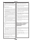
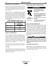
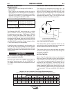
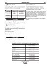
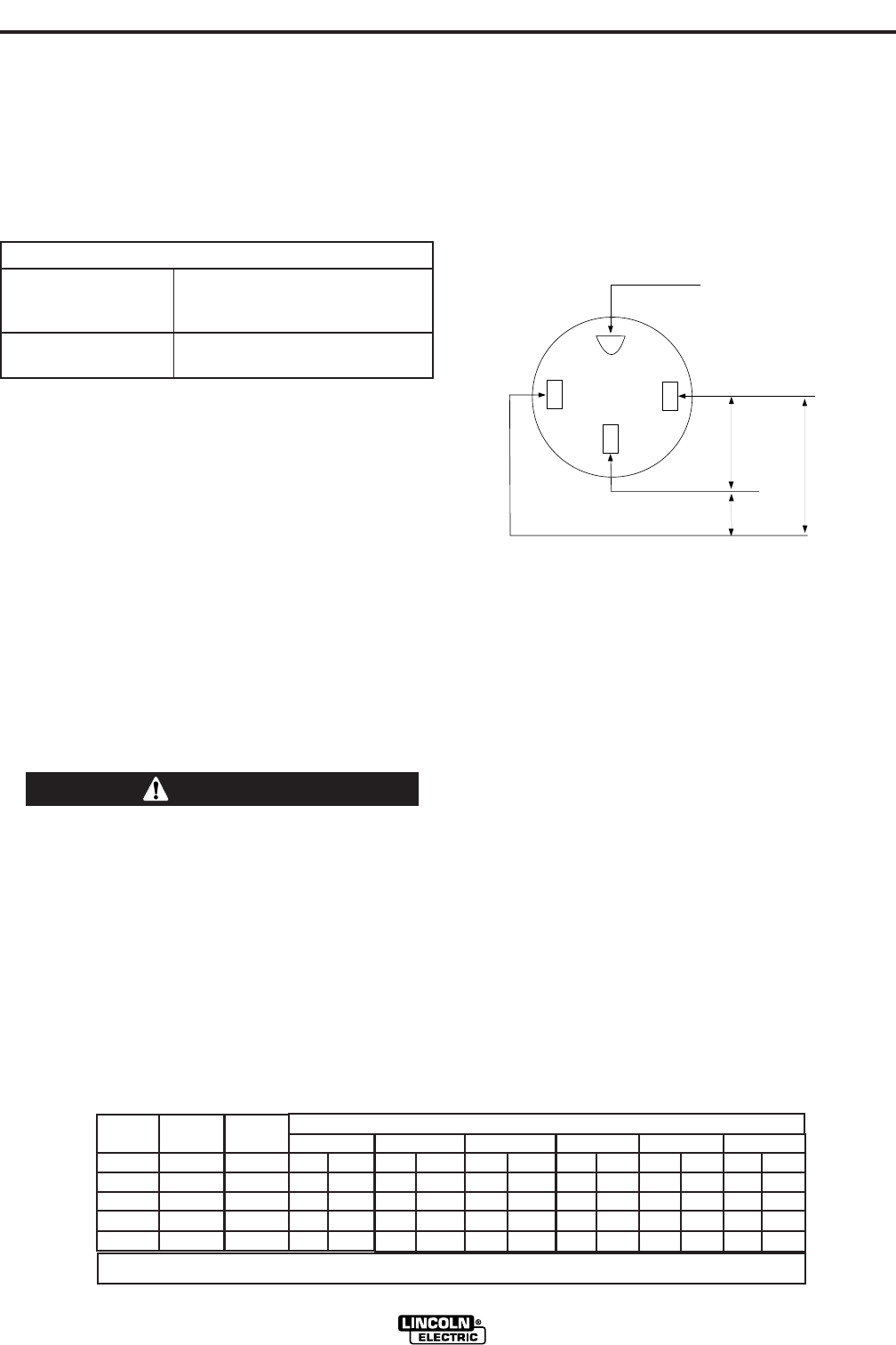
The 120/240 volt receptacle can supply up to 42
amps of 240 volt power to a two wire circuit, up to 42
amps of 120 volts power from each side of a three
wire circuit (up to 84 amps total). Do not connect the
120 volt circuits in parallel. Current sensing for the
automatic idle feature is only in one leg of the three
wire circuit as shown in the following column.
+*%!-'%)!(
The 120V auxiliary power receptacles should only be
used with three wire grounded type plugs or approved
double insulated tools with two wire plugs.
The current rating of any plug used with the system
must be at least equal to the current load through the
associated receptacle.
"$)$'()')#
Most 1.5 hp AC single phase motors can be started if
there is no load on the motor or other load connected
to the machine, since the full load current rating of a
1.5 hp motor is approximately 20 amperes (10
amperes for 240 volt motors). The motor may be run
at full load when plugged into only one side of the
duplex receptacle. Larger motors through 2 hp can be
run provided the receptacle rating as previously stated
is not exceeded. This may necessitate 240V operation
only.
GND
1
20 V
120 V*
240 V
*Current Sensing for Automatic Idle.
(Receptacle viewed from front of Machine)
GND
1
20 V
120 V*
240 V
*Current Sensing for Automatic Idle.
(Receptacle viewed from front of Machine)
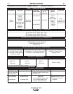
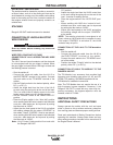
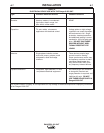
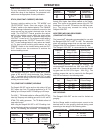
'1>75BQ-)HD5>C9?>?B4!5>7D8'53?==5>41D9?>C
(Use the shortest length extension cord possible sized per the following table.)
,!'$%')$#
,!'$*)%*)
• Maximum Open Circuit Voltage at 3700 RPM is
80 Volts RMS.
• Duty Cycle is the percentage of time the load is
being applied in a 10 minute period. For example, a
60% duty cycle represents 6 minutes of load and 4
minutes of no load in a 10 minute period. Duty
Cycle for the Ranger® 250 GXT is 100%.
*-!'.%$,'
The Ranger® 250 GXT can provide up to 10,000
watts of 120/240 volts AC, single phase 60Hz power
for continuous use, and up to 11,000 watts of 120/240
volts AC, single phase 60Hz power peak use. The
front of the machine includes three receptacles for
connecting the AC power plugs; one 50 amp 120/240
volt NEMA 14-50R receptacle and two 20 amp 120
volt NEMA 5-20R receptacles. Output voltage is within
+/-10% at all loads up to rated capacity.
All auxiliary power is protected by circuit breakers. the
120V has 20 Amp circuit breakers for each duplex
receptacle. The 120/240V Single Phase has a 50 Amp
2-pole Circuit Breaker that disconnects both hot leads
simultaneously.
?>?D3?>>53D1>I@<E7CD81D3?>>53DD?D85
@?G5BB535@D13<5C9>@1B1<<5<
------------------------------------------------------------------------
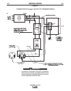
Start the engine and set the “IDLER” control switch to
the desired operating mode. Set the “CONTROL” to
10. Voltage is now correct at the receptacles for auxil-
iary power.
*)$#
Current
(Amps)
15
20
15
20
42
Voltage
Volts
120
120
240
240
240
Load
(Watts)
1800
2400
3600
4800
10,000
14 AWG
30 (9)
60 (18)
12 AWG
40 (19)
30 (9)
75 (23)
60 (18)
10 AWG
75 (23)
50 (15)
150 (46)
100 (30)
50 (15)
8 AWG
125 (38)
88 (27)
225 (69)
175 (53)
90 (27)
6 AWG
175 (53)
138 (42)
350 (107)
275 (84)
150 (46)
4 AWG
300 (91)
225 (69)
600 (183)
450 (137)
225 (69)
Conductor size is based on maximum 2.0% voltage drop.
Maximum Allowable Cord Length in ft. (m) for Conductor Size
'1>75BQ-)
?>CD1>DEBB5>D 250 Amps AC @ 25 Volts
250 Amps DC @ 25 Volts
?>CD1>D+?<D175 250 Amps DC @ 25 Volts