


A-4
INSTALLATION
POWER WAVE 455M (CE)
A-4
CABLE INDUCTANCE, AND ITS AFFECT
ON PULSE WELDING
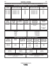
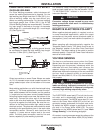
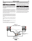
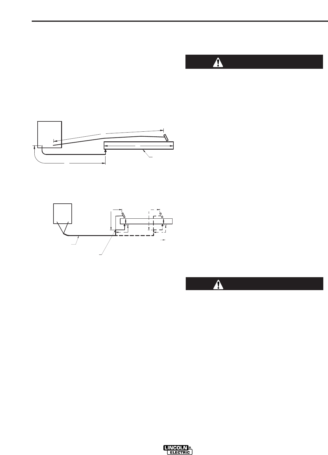
For Pulse Welding processes, cable inductance will
cause the welding performance to degrade. For the
total welding loop length less than 15.24m (50 ft.), tra-
ditional welding cables may be used without any
effects on welding performance. For the total welding
loop length greater than 15.24m (50 ft.), the K1796
Coaxial Welding Cables are recommended. The weld-
ing loop length is defined as the total of electrode
cable length (A) + work cable length (B) + work length
(C) (See Figure A.3).
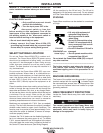
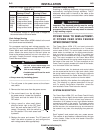
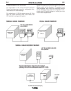
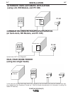
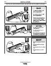
For long work piece lengths, a sliding ground should
be considered to keep the total welding loop length
less than 15.24m (50 ft.). (See Figure A.4.)
Output connections on some Power Waves are made
via 1/2-13 threaded output studs located beneath the
spring loaded output cover at the bottom of the case
front.
Most welding applications run with the electrode being
positive (+). For those applications, connect the elec-
trode cable between the wire feeder and the positive
(+) output stud on the power source (located beneath
the spring loaded output cover near the bottom of the
case front). Connect the other end of the electrode
cable to the wire drive feed plate. The electrode cable
lug must be against the feed plate. Be sure the con-
nection to the feed plate makes tight metal-to-metal
electrical contact. The electrode cable should be sized
according to the specifications given in the work cable
connections section. Connect a work lead from the
negative (-) power source output stud to the work
piece. The work piece connection must be firm and
secure, especially if pulse welding is planned.
For additional Safety information regarding the elec-
trode and work cable set-up, See the standard "SAFE-
TY INFORMATION" located in the front of the
Instruction Manuals.
Excessive voltage drops caused by poor work
piece connections often result in unsatisfactory
welding performance.
------------------------------------------------------------------------
NEGATIVE ELECTRODE POLARITY
When negative electrode polarity is required, such as
in some Innershield applications, switch the output
connections at the power source (electrode cable to
the negative (-) stud, and work cable to the positive (+)
stud).
When operating with electrode polarity negative the
"Electrode Sense Polarity" DIP switch must be set to
the "Negative" position on the Wire Drive Feed Head
PC Board. The default setting of the switch is positive
electrode polarity. Consult the Power Feed instruction
manual for further details.
VOLTAGE SENSING
The best arc performance occurs when the Power
Waves have accurate data about the arc conditions.
Depending upon the process, inductance within the
electrode and work lead cables can influence the
apparent voltage at the studs of the welder. Voltage
sense leads improve the accuracy of the arc conditions
and can have a dramatic effect on performance.
Sense Lead Kits (K940-10, -25 or -50) are available for
this purpose.
If the voltage sensing is enabled but the sense
leads are missing, improperly connected, or if the
electrode polarity switch is improperly configured,
extremely high welding outputs may occur.
------------------------------------------------------------------------
The ELECTRODE sense lead (67) is built into the con-
trol cable, and is automatically enabled for all semi-
automatic processes. The WORK sense lead (21) con-
nects to the Power Wave 455M (CE) at the four pin
connector located underneath the output stud cover.
By default the WORK voltage is monitored at the out-
put stud in the Power Wave 455M (CE). For more
information on the WORK sense lead (21), see "Work
Voltage Sensing” in the following paragraph.
All constant current processes sense the voltage at the
output studs of the Power Wave 455M (CE) by default.
CAUTION
CAUTION
B
A
C
FIGURE A.3
POWER
WAVE
WORK
A
C
B
POWER
WAVE
FIGURE A.4
K1796 COAXIAL CABLE
MEASURE FROM END
OF OUTER JACKET OF
CABLE
C
A
B
WORK
SLIDING WORK CONNECTION
FIGURE A.4