


A-6
INSTALLATION
POWER WAVE 455M (CE)
A-6
CONFIGURING THE SYSTEM
For codes below 11100, consult the semi-automatic
Power Feed instruction manual for configuration infor-
mation about DIP switch settings.
For codes above 11100 the power source will “Auto
Map” the system eliminating most of the need to set
DIP switches to configure the system.
If a system can not be “Auto Mapped” then the status
light on the power source will blink green fast and the
welder output will be disabled. If a system is not
“Auto-mappable”, then consult the instruction manual
for the accessory being used for configuration infor-
mation about DIP switch settings, or consult your local
Lincoln sales representative.
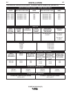
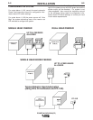
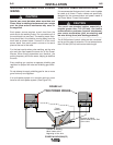
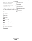
POWER WAVE
455M(CE)
ROBOT
PLC CONTROLLER
ANALOG INTERFACE
etc.
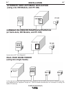
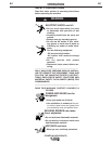
POWER WAVE 455M(CE)
POWER WAVE
455M(CE)
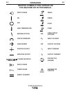
POWER WAVE
455M(CE)
FEED HEAD
SINGLE HEAD FEEDER DUAL HEAD FEEDER
SINGLE HEAD BOOM FEEDER
FH 1
PF-10R
Typical Robotic/ Hard Automation
(using Wire Drive Module and PF-10R)
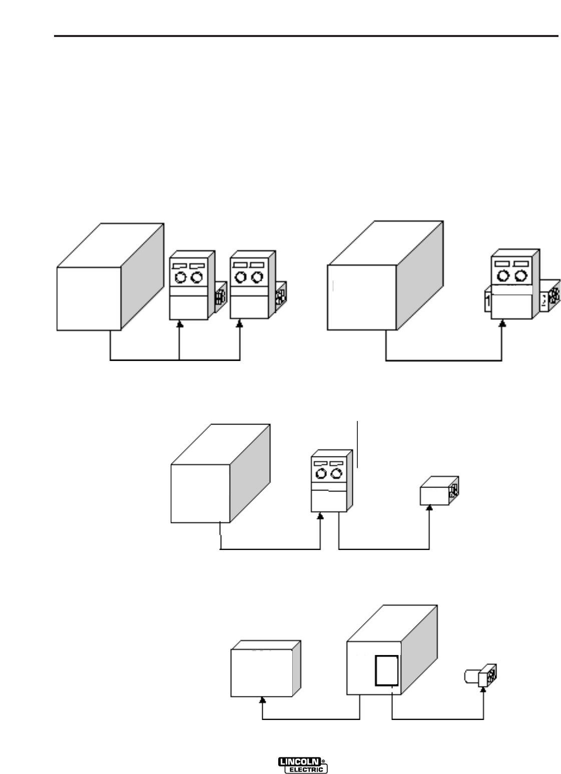
UP TO 4 FEEDERS
ALLOWED
UP TO 4 FEED HEADS
ALLOWED
WIRE
DRIVE
MODULE