


B-3
OPERATION
B-3
CHECKING AIR QUALITY
To check air quality, deactivate the torch (post-flow)
and place a welding filter lens in front of the torch. Any
oil or moisture in the air will be visible on the lens. DO
NOT initiate pilot arc while checking air quality.
When preparing to cut, position the machine as close
to the work as possible. Make sure you have all
materials needed to complete the job and have taken
all safety precautions. It is important to follow these
operating steps each time you use the machine.
• COMPRESSED AIR
The PLASMA 20 requires compressed air to be
attached to the unit. The input air pressure mini-
mum must be 72.5 PSI, 5 Bar and must not exceed
150 PSI, 10.3 Bar. An air regulator is included with
the unit with optimum pressure setting set to 65
PSI, 4.5 Bar.
The unit is also equipped with an air filter which cap-
tures water and oil vapor. The vapor collected can
be drained out of the bottom of the unit by turning
the drain button. The unit will not operate if the
input air pressure is below 55 PSI, 3.8 Bar.
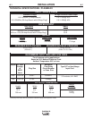
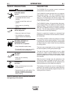
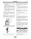
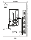
Three Position Drain knob: (See Figure B.1)
1. Open
2. Open when no air pressure, closed when air pres-
sure.
3. Closed
CUTTING WITH A HAND TORCH
• Turn the main power and the machine power switch
on.
- The fan should start.
- The pre-charge circuit will operate for 3 seconds,
then the green "Power" LED should turn on.
• Be sure that the work lead is clamped to the work-
piece before cutting.
• Set the output current control knob at maximum
position for higher cutting speed and less dross for-
mation. Reduce the current, if desired to reduce the
kerf (cut) width, heat affected zone or travel speed
as required.
PLASMA 20
CUTTING OPERATIONS
BEFORE CUTTING
ELECTRIC SHOCK CAN KILL.
Disconnect input power by removing
the plug from the receptacle before
assembling or disassembling torch
parts, or torch and lead assemblies.
------------------------------------------------------------------------
Check and follow instructions listed in the “Safety and
Installation” section of this manual.
TORCH PARTS
Check the torch for proper assembly. Install proper
torch parts for the desired application (refer to the
Torch Consumable Parts Selection Section).
NOTE: The power supply will not operate unless the
torch shield cup is fully seated against the PIP
(Parts in Place) pins in the torch head.
INPUT POWER
Check the power source for proper input voltage.
Make sure the power source meets circuit protection
and wiring requirements.
Plug in power cord to supply input power to the unit.
GROUND CABLE
Check for a solid ground cable connection to the
workpiece.
AUTOMATIC PURGE SYSTEM
Place the ON/OFF switch to the ON position. If the
line voltage is OK, the green LED will turn on. Activate
the torch trigger to initiate air purge. There will be a 3
second delay to remove any condensation that may
have accumulated in the torch and air lines while the
system was shut down. When the air purge (Air safety
time) is complete, pilot arc will be initiated.
FIGURE B.1
WARNING
KNOB