


A-2
INSTALLATION
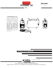
PLASMA 20
A-2
Read entire Installation Section before installing the
PLASMA 20.
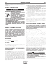
SAFETY PRECAUTIONS
ELECTRIC SHOCK CAN KILL.
• Only qualified personnel should
perform this installation.
• Only personnel that have read and
understood the PLASMA 20
Operating Manual should install
and operate this equipment.
• Machine must be plugged into a receptacle
which is grounded per any national, local or
other applicable electrical codes.
• The PLASMA 20 power switch is to be in the OFF
(“O”) position when installing work cable and
gun and when connecting power cord to input
power.
___________________________________________
SELECT PROPER LOCATION
Place the PLASMA 20 where clean cool air can freely
circulate in and out the front, rear and side louvers.
Dirt, dust, smoke, gas or any foreign material that can
be drawn into the machine should be kept at a mini-
mum. Insure open space of at least 15 ft. around the
machine. Failure to observe these precautions can
result in excessive operating temperatures and nui-
sance shutdown of the machine.
STACKING
The PLASMA 20 cannot be stacked.
TILTING
The PLASMA 20 must be placed on a stable, level
surface so it will not topple over.
HIGH FREQUENCY INTERFERENCE
PROTECTION
The PLASMA 20 employs a touch start mechanism for
arc initiation which eliminates high frequency emis-
sions from the machine as compared with spark gap
and solid state type high frequency generators. Keep
in mind, though, that these machines may be used in
an environment where other high frequency generat-
ing machines are operating. By taking the following
steps, high frequency interference into the PLASMA
20 can be minimized.
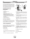
(1) Make sure the power supply chassis is connected
to a good earth ground. The work terminal ground
does NOT ground the machine frame.
(2) Keep the work clamp isolated from other work
clamps that have high frequency.
(3) If the work clamp cannot be isolated, then keep
the clamp as far as possible from other work
clamp connections.
(4) When the machine is enclosed in a metal building,
several good earth driven electrical grounds
around the periphery of the building are recom-
mended.
Failure to observe these recommended installation
procedures may cause improper function of the PLAS-
MA 20 or possibly even damage to the control system
or power supply components.
INPUT ELECTRICAL CONNECTIONS
The PLASMA 20 must be connected to a Line-Neutral
system with protective grounding wire. Check that the
relevant electrical outlet is actually connected to the
distribution system grounding.
The PLASMA 20 is rated for 115VAC input.
Use on 15 amp branch circuits will limit cutting output.
When the output is set at 16 amps or greater, the
input fuse or circuit breaker may “blow” in roughly 30
seconds or less (depending on fuse or circuit breaker
type).
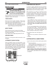
To achieve 16-20 amp output with 115VAC input,
replace the 15 amp plug on the input cord with a 20
amp plug, and connect the unit to a 20 amp branch
circuit with super lag fuses (or equivalent breaker). To
install 20 amp plug: Connect the white (neutral) wire
under terminal clamp with silver screw, and black (hot)
wire under terminal clamp with brass screw. Connect
green wire under terminal clamp with green screw.
Tighten terminal wire clamp screws securely.
5-20P plug must comply with the standard for attach-
ment plugs and receptacles, UL498. This product is
acceptable for use only when an attachment plug as
specified is properly attached to the supply cord.
• Failure to wire as instructed may cause personal
injury or damage to equipment.
• To be installed or checked by an electrician or
qualified person only.
------------------------------------------------------------------------
WARNING
WARNING