


B-5
OPERATION
B-5
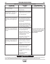
OPERATING FAULTS
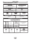
During cutting operations performance faults may
arise, such as:
• Insufficient penetration:
too high cutting speed;
torch is tilted;
piece is too thick;
cutting current is too low;
torch parts are worn out;
non-genuine Manufacturer’s parts.
• Interruption of the cutting arc:
cutting speed too slow;
excessive distance between torch and work
piece;
Input Voltage too low-reduce output current;
torch parts are worn out;
non-genuine Manufacturer’s parts;
poor work cable connection/disconnected.
• Excessive slag/dross:
too low cutting speed (bottom dross);
too high cutting speed (top dross);
excessive distance between torch and work
piece;
cutting current too low;
torch parts are worn out;
non-genuine Manufacturer’s parts.
• Tilted cutting (not perpendicular):
torch position not correct;
asymmetric wear of nozzle hole and/or
incorrect assembly of the torch parts.
• Excessive wear of nozzle and electrodes:
air pressure too low;
exceeding system capability (material too
thick);
contaminated air (humidity/oil);
excessive pilot arc ignitions in the air;
improperly assembled torch;
torch nozzle contacting workpiece;
damaged or loose torch head components;
non-genuine Manufacturer’s parts.
PLASMA 20
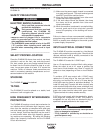
PILOT ARC DISCUSSION
The PLASMA 20 has a smooth, continuous pilot arc. The
pilot arc is only a means of transferring the arc to the work-
piece for cutting. Repeated pilot arc starts, in rapid succes-
sion, is not recommended as these starts will generally
reduce consumable life. Occasionally, the pilot arc may
sputter or start intermittently. This is aggravated when the
consumables are worn or the air pressure is too high.
Always keep in mind that the pilot arc is designed to transfer
the arc to the workpiece and not for numerous starts without
cutting.
When the pilot arc is started, a slight impulse will be felt in
the torch handle. This occurrence is normal and is the
mechanism which starts the plasma arc. This impulse can
also be used to help troubleshoot a "no start" condition.
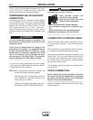
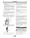
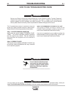
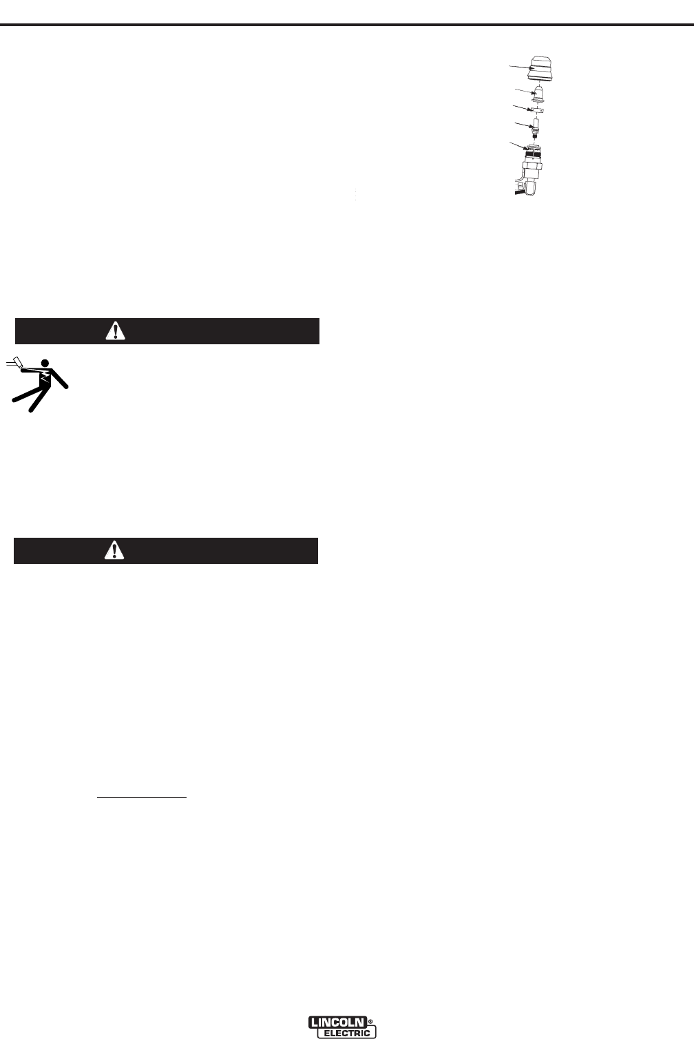
S
HEILD CUP
NOZZLE
ELECTRODE
T
ORCH HEAD
A
SSEMBLY
GAS DIFFUSER RING
FIGURE B.2
ELECTRIC SHOCK CAN KILL.
Disconnect input power by removing
the plug from the receptacle before
assembling or disassembling torch
parts, or torch and lead assemblies.
--------------------------------------------------------------------------------
WARNING
Be sure the operator is equipped with proper gloves,
clothing, eye and ear protection. Make sure no part of
the operator’s body comes in contact with the work
piece while the torch is activated.
Sparks from the cutting process can cause dam-
age to coated, painted, and other surfaces such as
glass, plastic and metal.
NOTE: Handle torch cable with care and protect
it from damage.
------------------------------------------------------------------------
TORCH CONSUMABLE PARTS
SELECTION
To change the torch consumable parts use the follow-
ing procedure:
NOTE: The nozzle, gas distributor, and electrode are
held in place by the shield cup. Position the torch with
the shield cup facing upward
to prevent these parts
from falling out when the cup is removed.
1. Unscrew and remove the shield cup from the Torch
Head Assembly. Figure B.2 Consumable Parts.
2. Remove the nozzle, gas distributor, and electrode.
3. Install the electrode, gas distributor and nozzle.
4. Hand tighten the shield cup until it is seated on the
torch head. If resistance is felt when installing the
cup, check the threads before proceeding.
CAUTION