


A-3
INSTALLATION
TOMAHAWK™ 625
A-3
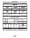
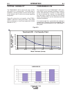
The following Lincoln engine drives meet these condi-
tions when run in the high idle mode:
Outback 189, Ranger 225, 250, 250LPG, 305G and
305D engine drives.
Vantage 300, 400, 500 and Air Vantage engine drives.
Some engine drives do not meet these conditions
(e.g. Miller Bobcats, etc). Operation of the TOMA-
HAWK™ 625 is not recommended on engine drives
not conforming to these conditions. Such combina-
tions may overvoltage the TOMAHAWK™ 625 power
source.
GAS INPUT CONNECTIONS
(External Air Supply)
Supply the TOMAHAWK™ 625 with clean com-
pressed air or nitrogen.
• Supply pressure must be between 80 psi
and 110 psi.
• Flow rate should be approximately 125 - 200
SCFH (80 ±20 L/min).
NOTE: Oil in the air supply to the TOMAHAWK™ 625
can cause severe problems. Use only a clean
air supply.
•
Compressed gas can be supplied either through the air
fitting supplied with the machine or through the 1/4-19
BSPP
thread at the rear of the machine. To use the air
fitting supplied with the machine (packaged in the con-
sumable kit), apply teflon tape to the fitting threads and
install the fitting in the port at the rear of the machine.
• If compressed air is being used, it is highly recom-
mended that an in line filter be installed in the air
supply line ahead of the air connection to the TOMA-
HAWK™ 625.
• A standard nominal 5 micron in line filter is recom-
mended; however, for optimum performance, select
a prefilter with a 3 micron absolute rating.
If these filter ratings are unavailable, anything with a
rating less than, or equal to, 20 micron would be
acceptable to use. In line filter elements will generally
filter the air with little restriction to the airflow until the
element is about 75% contaminated. After this point,
there will be a noticeable pressure drop in the line.
Filter elements should be replaced when a pressure
drop of 8-10 psi is indicated; however, for optimum
performance of the TOMAHAWK™ 625, the filter ele-
ment should be replaced at or before the pressure
drop reaches 8 psi. Be sure to select a filter that will
accommodate the necessary flow rating for the TOM-
AHAWK™ 625 as specified in the Installation section
of this instruction manual under the Gas Input
Connections heading.
NOTE: When using nitrogen gas from a cylinder, the
cylinder must have a pressure regulator.
• Maximum psi from a nitrogen gas cylinder to
the TOMAHAWK™ 625 regulator should
never exceed 110 psi.
• Install a hose between the nitrogen gas cylin-
der regulator and the TOMAHAWK™ 625 gas
inlet.
.
CYLINDER could explode if dam-
aged.
• Keep cylinder upright and
chained to a fixed support.
• Keep cylinder away from areas
where it could be damaged.
• Never lift machine with cylinder attached.
• Never allow the cutting torch to touch the
cylinder.
• Keep cylinder away from live electrical
parts.
• Maximum inlet pressure 110 psi.
------------------------------------------------------------------------
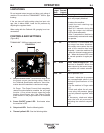
OUTPUT CONNECTIONS
Torch
The TOMAHAWK™ 625 is sent from the factory with
a cutting torch and work clamp included. The work
clamp must be securely connected to the work piece.
If the work piece is painted or extremely dirty it may
be necessary to expose the bare metal in order to
make a good electrical connection.
WARNING