


B-3
OPERATION
B-3
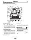
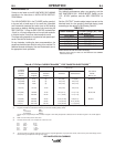
7. OIL PRESSURE GAUGE
The gauge displays the engine oil pressure when
the engine is running.
8. ENGINE PROTECTION
The yellow engine protection light remains off
with proper oil pressure and under normal oper-
ating temperatures. If the light turns on, the
engine protection system will stop the engine.
Check for proper oil level and add oil if neces-
sary. Check for loose or disconnected leads at
the oil pressure sender located on the engine.
The light will remain on when the engine has
been shut down due to low oil pressure or over-
temperature condition.
9. BATTERY CHARGING LIGHT
The yellow engine alternator light is off when bat-
tery charging system is functioning normally. If
light turns on the alternator or the voltage regula-
tor may not be operating correctly. The light will
remain on when the engine is stopped and the
run/stop switch is in the run position.
10. IDLER SWITCH
Has two positions as follows:
A) In the “High” position , the engine runs at
the high idle speed controlled by the governor.
B) In the “Auto” / position, the
idler operates as follows:
a. When switched from “High” to “Auto” or after
starting the engine, the engine will operate at
full speed for approximately 12 seconds and
then go to low idle speed.
b. When the electrode touches the work or power
is drawn for lights or tools (approximately 100
Watts minimum) the engine accelerates and
operates at full speed.
c. When welding ceases and the AC power load
is turned off, a fixed time delay of approximate-
ly 12 seconds starts.
d. If the welding or AC power load is not restart-
ed before the end of the time delay, the idler
reduces the engine speed to low idle speed.
e. The engine will automatically return to high
idle speed when the welding load or A.C.
power load is reapplied.
Idler Operational exceptions
When the WELDING TERMINALS switch is in
the “Remotely Controlled” position the idler will
operate as follows:
a. When the triggering device (Amptrol, Arc Start
Switch, etc.) is pressed the engine will acceler-
ate and operate at full speed provided a weld-
ing load is applied within approximately 12
seconds.
• If the triggering device remains pressed but no
welding load is applied within approximately 12
seconds the engine may return to low idle
speed.
• If the triggering device is released or welding
ceases the engine will return to low idle speed
after approximately 12 seconds.
WELDING CONTROLS (Items 11
through 20)
11. OUTPUT CONTROL:
The OUTPUT dial is used to preset the output
voltage or current as displayed on the digital
meters for the four welding modes. When in the
CC-STICK or CV-WIRE modes and when a
remote control is connected to the 6-Pin or 14-
Pin Connector, the auto-sensing circuit automati-
cally switches the OUTPUT CONTROL from con-
trol at the welder to the remote control. In the
CV-WIRE mode, when the wire feeder control
cable is connected to the 14-Pin Connector, the
auto-sensing circuit automatically makes OUT-
PUT CONTROL inactive and the wire feeder volt-
age control active.
When in the TOUCH START TIG mode and
when a Amptrol is connected to the 6-Pin
Connector, the OUTPUT dial is used to set the
maximum current range of the CURRENT CON-
TROL of the Amptrol.
12. DIGITAL OUTPUT METERS:
The digital meters allow the output voltage (CV-
WIRE mode) or current (CC-STICK and TIG
modes) to be set prior to welding using the OUT-
PUT control knob. During welding, the meters
display the actual output voltage (VOLTS) and
current (AMPS). A memory feature holds the dis-
play of both meters on the seven seconds after
welding is stopped. This allows the operator to
read the actual current and voltage just prior to
when welding was ceased. While the display is
being held the left-most decimal point in each
display will be flashing. The accuracy of the
meters is ± 3%.
AIR VANTAGE® 500 CUMMINS