


PARALLELING
When paralleling machines in order to combine their
outputs, all units must be operated in the CC-STICK
mode only at the same output settings. To achieve
this, turn the WELD MODE switch to the CC-STICK
position. Operation in other modes may produce errat-
ic outputs, and large output imbalances between the
units.
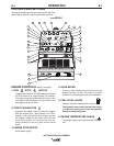
AUXILIARY POWER OPERATION
Start the engine and set the IDLER control switch to
the desired operating mode. Full power is available
regardless of the welding control settings, if no weld-
ing current is being drawn.
The auxiliary power of the AIR VANTAGE® 500 con-
sists of two 15Amp 240VAC single phase receptacles.
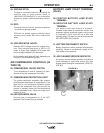
The auxiliary power receptacles should only be used
with three wire grounded type plugs or approved dou-
ble insulated tools with two wire plugs.
The current rating of any plug used with the system
must be at least equal to the current capacity of the
associated receptacle.
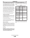
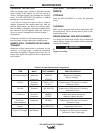
SIMULTANEOUS WELDING AND AUXIL-
IARY POWER LOADS
It must be noted that the above auxiliary power ratings
are with no welding load.
Simultaneous welding and power loads are specified
in table B.4.
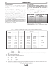
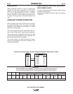
AIR VANTAGE® 500 CUMMINS Extension Cord Length Recommendations
(Use the shortest length extension cord possible sized per the following table.)
AIR VANTAGE® 500 CUMMINS
B-10
OPERATION
B-10
TABLE B.5
TABLE B.4 AIR VANTAGE® 500 SIMULTANEOUS WELDING AND POWER LOADS
WELD
AMPS
0
100
200
250
300
400
500
1 PHASE
WATTS AMPS
7,200 30
7,200 30
7,200 30
7,200 30
7,200 30
5,600 23
0 0
PLUS
Maximum Allowable Cord Length in ft. (m) for Conductor Size
Conductor size is based on maximum 2.0% voltage drop.
14AWG 2.5
2
mm 12AWG 4.0
2
mm 10AWG 6.0
2
mm 8AWG 10.0
2
mm 6AWG 16.0
2
mm 4AWG 25.0
2
mm
Load
(Watts)
3600
Current
(Amps)
15
Voltage
(Volts)
240
60
(18)
75 (23) 150
46 225
(69) 350 107
600 (183)