


ARC GOUGING
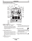
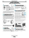
For optimal performance when arc gouging, set the
VANTAGE® 575 CUMMINS
“WELD MODE” switch to
the “CC - STICK” position, and the “ARC CONTROL”
to 10.
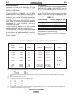
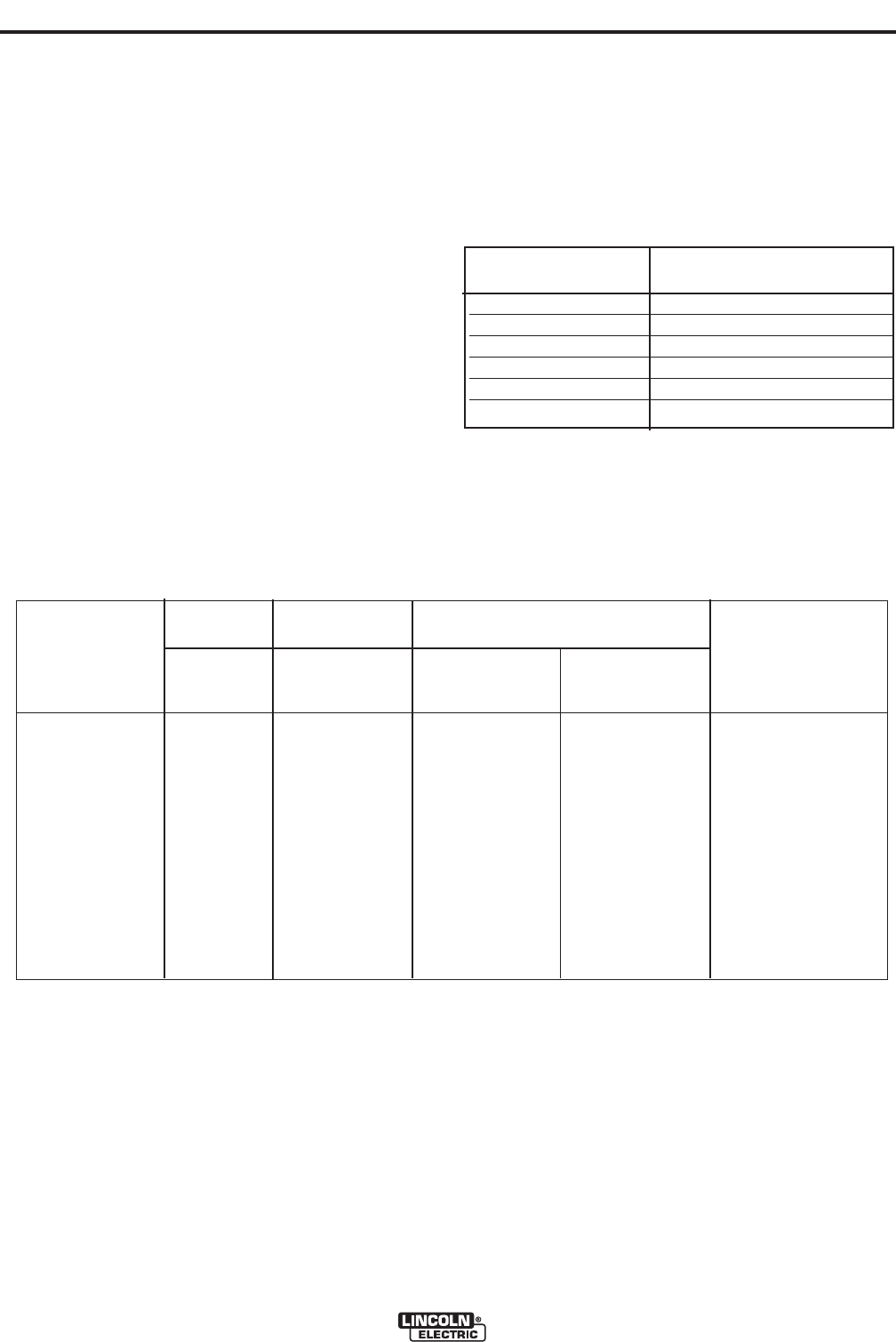
Set the “OUTPUT” knob to adjust output current to the
desired level for the gouging electrode being used
according to the ratings in the
following Table B.2
NOTE: If desired the CV mode can be used for Arc Gouging.
* Maximum current setting is limited to the VANTAGE® 575 CUMMINS maxi-
mum of 575 Amps.
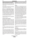
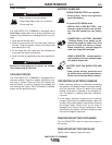
WIRE WELDING-CV
Connect a wire feeder to the VANTAGE® 575 CUM-
MINS according to the instructions in INSTALLATION
INSTRUCTIONS Section.
The VANTAGE® 575 CUMMINS in the ”CV-WIRE”
position, permits it to be used with a broad range of
flux cored wire (Innershield and Outershield) elec-
trodes and solid wires for MIG welding (gas metal arc
welding). Welding can be finely tuned using the “ARC
CONTROL”. Turning the ARC CONTROL clockwise
from -10(soft) to +10(crisp) changes the arc from soft
and washed-in to crisp and narrow. It acts as an
inductance/pinch control.
The proper setting depends on the procedure and
operator preference. Start with the knob set at 0.
For any electrodes, including the above recommenda-
tions, the procedures should be kept within the rating
of the machine. For additional electrode information,
See www.lincolnelectric.com or the appropriate
Lincoln publication.
Carbon Diameter
Current Range (DC, elec-
trode positive)
1/8"(3.2mm) 30-60 Amps
5/32"(4.0mm) 90-150 Amps
3/16"9(4.8mm) 200-250 Amps
1/4"(6.4mm) 300-400 Amps
5/16"(8.0mm) 350-450 Amps
3/8"(10.0mm) 450-575 Amps*
TABLE B.2
B-9
OPERATION
B-9
VANTAGE® 575 CUMMINS
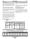
Table B.3 TYPICAL CURRENT RANGES
(1)
FOR TUNGSTEN ELECTRODES
(2)
DCEN (-) DCEP (+) Approximate Argon Gas Flow Rate
l/min (c.f.m.)
Tungsten
Electrode 1%, 2% 1%, 2% TIG TORCH
Diameter Thoriated Thoriated Aluminium Stainless Steel Nozzle
mm (in) Tungsten Tungsten Size (4), (5)
.25 (0.010) 2-15 (3) 2-4 (3-8) 2-4 (3-8) #4, #5, #6
.50 (0.020) 5-20 (3) 3-5 (5-10) 3-5 (5-10)
1.0 (0.040) 15-80 (3) 3-5 (5-10) 3-5 (5-10)
1.6 (1/16) 70-150 10-20 3-5 (5-10) 4-6 (9-13) #5, #6
2.4 (3/32) 150-250 15-30 6-8 (13-17) 5-7 (11-15) #6, #7, #8
3.2 (1/8) 250-400 25-40 7-11 (15-23) 5-7 (11-15)
4.0 (5/32) 400-500 40-55 10-12 (21-25) 6-8 (13-17) #8, #10
4.8 (3/16) 500-750 55-80 11-13 (23-27) 8-10 (18-22)
6.4 (1/4) 750-1000 80-125 13-15 (28-32) 11-13 (23-27)
(1) When used with argon gas. The current ranges shown must be reduced when using argon/helium or pure helium shielding gases.
(2) Tungsten electrodes are classified as follows by the American Welding Society (AWS):
Pure EWP
1% Thoriated EWTh-1
2% Thoriated EWTh-2
Though not yet recognized by the AWS, Ceriated Tungsten is now widely accepted as a substitute for 2% Thoriated Tungsten in AC and DC applica-
tions.
(3) DCEP is not commonly used in these sizes.
(4) TIG torch nozzle “sizes” are in multiples of 1/16ths of an inch:
# 4 = 1/4 in. 6 mm
# 5 = 5/16 in. 8 mm
# 6 = 3/8 in. 10 mm
# 7 = 7/16 in. 11 mm
# 8 = 1/2 in. 12.5 mm
#10 = 5/8 in. 16 mm
(5) TIG torch nozzles are typically made from alumina ceramic. Special applications may require lava nozzles, which are less prone to breakage, but can-
not withstand high temperatures and high duty cycles.