


PARALLELING
When paralleling machines in order to combine their
outputs, all units must be operated in the CC-STICK
mode only at the same output settings. To achieve
this, turn the WELD MODE switch to the CC-STICK
position. Operation in other modes may produce errat-
ic outputs, and large output imbalances between the
units.
AUXILIARY POWER OPERATION
Start the engine and set the IDLER control switch to
the desired operating mode. Full power is available
regardless of the welding control settings, if no weld-
ing current is being drawn.
The auxiliary power of the VANTAGE® 575 CUM-
MINS consists of two 15 Amp-240V single phase
receptacles and one 32amp-415V 3 phase receptacle.
The auxiliary power capacity is 7,200 watts of 50 Hz,
single phase power or 20,000 watts of 50Hz, three
phase power. The auxiliary power capacity rating in
watts is equivalent to volt-amperes at unity power fac-
tor. The maximum permissible current of the 415 VAC
output is 32 A.Output voltage is within ±10% at all
loads up to rated capacity.
NOTE: The 240V receptacles are connected to differ-
ent phases and cannot
be paralleled.
The auxiliary power receptacles should only be used
with three wire, four wire or fire wire earth type plugs
or approved double insulated tools with two wire
plugs.
The current rating of any plug used with the system
must be at least equal to the current capacity of the
associated receptacle.
SIMULTANEOUS WELDING AND
AUXILIARY POWER LOADS
It must be noted that the above auxiliary power ratings
are with no welding load. Simultaneous welding and
power loads are specified in table B.4. The permissi-
ble currents shown assume that current is being
drawn from either the 240 VAC or 415 VAC supply
(not both at the same time).
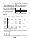
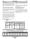
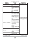
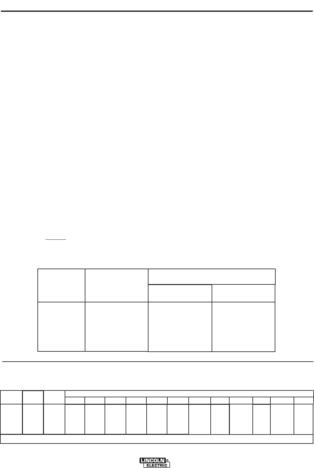
VANTAGE® 575 CUMMINS Extension Cord Length Recommendations
(Use the shortest length extension cord possible sized per the following table.)
VANTAGE® 575 CUMMINS
B-10
OPERATION
B-10
TABLE B.5
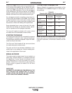
TABLE B.4 VANTAGE® 575 CUMMINS SIMULTANEOUS WELDING AND POWER LOADS
WELDING
OUTPUT
500A/40V
350A/34V
200A/30V
150A/26V
90A/24V
0
PERMISSIBLE
POWER-WATTS
(Unity Power Factor)
0
8,100
12,000
16,000
18,000
20,000
@ 240V ±10%*
0
40*
30*
30*
30*
30*
@ 415V ±10%
0
14 amp/phase
18.5 amp/phase
23.6 amp/phase
26.4 amp/phase
32 amp/phase
Maximum Allowable Cord Length in m (ft.) for Conductor Size
Conductor size is based on maximum 2.0% voltage drop.
2.5
2
mm 14AWG 4.0
2
mm 12AWG 6.0
2
mm 10AWG 10.0
2
mm 8AWG 16.0
2
mm 6AWG 25.0
2
mm 4AWG
Load
(Watts)
3,600
4,800
Current
(Amps)
15
20
Voltage
(Volts)
240
240
18
(60)
23
18
(75)
(60)
46
30
(150)
(100)
69
53
(225)
(175)
107
84
(350)
(275)
183
137
(600)
(450)
Permissible Auxiliary
Current in Amperes
* Each receptacle is limited to 15 amps.