


AUXILIARY POWER:
Start the engine and set the IDLER control switch to
the desired operating mode. Full power is available
regardless of the welding control settings providing no
welding current is being drawn.
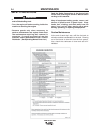
Simultaneous Welding and Auxiliary Power Loads
The auxiliary power ratings are with no welding load.
Simultaneous welding and power loads are specified
in Table B.5.
VANTAGE® 580
B-7
OPERATION
B-7
This will keep the "Solid State" contactor open and provide a
"cold" electrode until the Amptrol or Arc Start Switch is pressed.
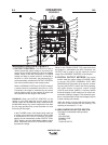
When using the TIG Module, the OUTPUT CONTROL on the
VANTAGE® 580 is used to set the maximum range of the CUR-
RENT CONTROL on the TIG Module or an Amptrol if connect-
ed to the TIG Module.
NOTE: The TIG process is to receive a low voltage welding
process. There is no difference in operation with the
VRD “On” or “Off” for this mode. For indicator light oper-
ation, see
Table B.1
.
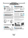
WIRE WELDING-CV
Connect a wire feeder to the VANTAGE® 580 according to the
instructions in INSTALLATION INSTRUCTIONS Section.
The VANTAGE® 580 in the CV-WIRE mode, permits it to be
used with a broad range of flux cored wire (Innershield and
Outershield) electrodes and solid wires for MIG welding (gas
metal arc welding). Welding can be finely tuned using the ARC
CONTROL. Turning the ARC CONTROL clockwise from –10
(soft) to +10 (crisp) changes the arc from soft and washed-in to
crisp and narrow. It acts as an inductance/pinch control. The
proper setting depends on the procedure and operator prefer-
ence. Start with the dial set at 0.
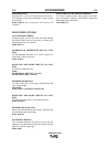
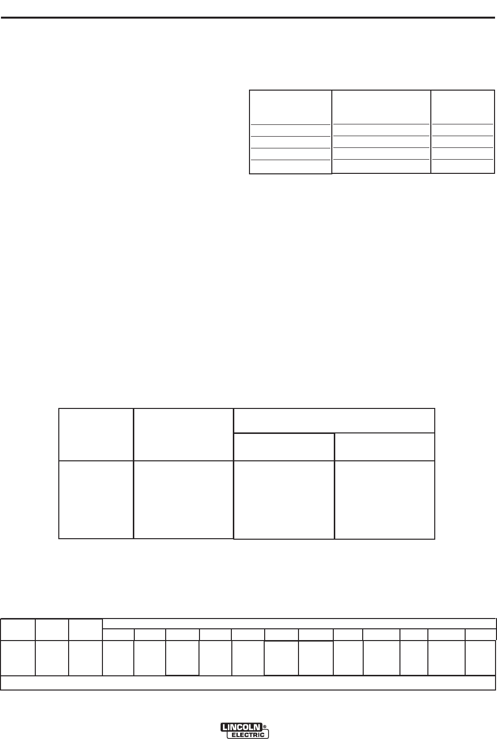
ARC GOUGING
The VANTAGE® 580 can be used for arc gouging. For
optimal performance, set the MODE per TABLE B.4.
Set the OUTPUT CONTROL knob to adjust output
current to the desired level for the gouging electrode
being used according to the ratings in the following
Table B.4.
TABLE B.4
The ARC CONTROL is not active in the ARC GOUG-
ING Mode. The ARC CONTROL is automatically set
to maximum when the ARC GOUGING mode is
selected which provides the best ARC GOUGING per-
formance.
TABLE B.5 VANTAGE® 580 PERKINS SIMULTANEOUS WELDING AND POWER LOADS
WELDING
OUTPUT
500A/40V
350A/34V
200A/30V
150A/26V
90A/24V
0
PERMISSIBLE
POWER-WATTS
(Unity Power Factor)
0
8,100
12,000
16,000
18,000
20,000
@ 240V ±10%*
0
30*
30*
30*
30*
30*
@ 415V ±10%
0
14 amp/phase
18.5 amp/phase
23.6 amp/phase
26.4 amp/phase
28 amp/phase
Permissible Auxiliary
Current in Amperes
* Each receptacle is limited to 15 amps.
VANTAGE® 580 PERKINS Extension Cord Length Recommendations
(Use the shortest length extension cord possible sized per the following table.)
TABLE B.6
Maximum Allowable Cord Length in m (ft.) for Conductor Size
Conductor size is based on maximum 2.0% voltage drop.
2.5
2
mm 14AWG 4.0
2
mm 12AWG 6.0
2
mm 10AWG 10.0
2
mm 8AWG 16.0
2
mm 6AWG 25.0
2
mm 4AWG
Load
(Watts)
3,600
Current
(Amps)
15
Voltage
(Volts)
240
18
(60)
23 (75) 46
(150) 69
(225)
107
(350)
183 (600)
Carbon Diameter
1/8"(3.2mm)
5/32"(4.0mm)
3/16"9(4.8mm)
1/4"(6.4mm)
3/8"(10.0mm)
Current Range (DC,
electrode positive)
60-90 Amps
90-150 Amps
200-250 Amps
300-400 Amps
400-Max.Amps
Mode
CC-STICK
CC-STICK
ARC GOUGE
ARC GOUGE
ARC GOUGE