


&("""$
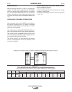
When paralleling machines in order to combine their
outputs, all units must be operated in the CC-STICK
mode only at the same output settings. To achieve
this, turn the WELD MODE switch to the CC-STICK
position. Operation in other modes may produce errat-
ic outputs, and large output imbalances between the
units.
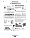
+."(/&%-(%&(*%$
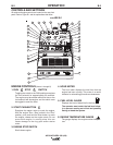
Start the engine and set the IDLER control switch to
the desired operating mode. Full power is available
regardless of the welding control settings, if no weld-
ing current is being drawn.
The auxiliary power of the AIR VANTAGE® 500 con-
sists of two 15Amp 240VAC single phase receptacles.
The auxiliary power receptacles should only be used
with three wire grounded type plugs or approved dou-
ble insulated tools with two wire plugs.
The current rating of any plug used with the system
must be at least equal to the current capacity of the
associated receptacle.
)#+"*$%+) -"$$+."
(/&%-("%)
It must be noted that the above auxiliary power ratings
are with no welding load.
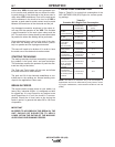
Simultaneous welding and power loads are specified
in table B.4.
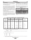
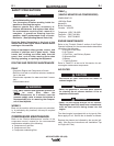
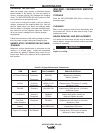
(,$*Q+ IE6?D:@?@C5"6?8E9(64@>>6?52E:@?D
(Use the shortest length extension cord possible sized per the following table.)
(,$*Q+
%&(*%$
*"
*"(,$*Q)#+"*$%+)-"$$&%-("%)
-"
#&)
0
100
200
250
300
400
500
&)
-**) #&)
7,200 30
7,200 30
7,200 30
7,200 30
7,200 30
5,600 23
0 0
&"+)
Maximum Allowable Cord Length in ft. (m) for Conductor Size
Conductor size is based on maximum 2.0% voltage drop.
14AWG 2.5
2
mm 12AWG 4.0
2
mm 10AWG 6.0
2
mm 8AWG 10.0
2
mm 6AWG 16.0
2
mm 4AWG 25.0
2
mm
Load
(Watts)
3600
Current
(Amps)
15
Voltage
(Volts)
240
60
(18)
75 (23) 150
46 225
(69) 350 107
600 (183)