


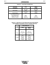


2.17 DUAL PROCEDURE SWITCH COM-
MAND
This is an active low output from the robot con-
troller used to activate the dual procedure switch.
When the Power Wave is running a dual proce-
dure overlay this output is used to switch
between procedures. If the output is held high
by the robot controller then procedure A is active,
and if the output is held low then procedure B is
active.
2.18 WIRE STICK DETECT
This is a resistance measuring input to the robot
controller used to detect a wire stick. The
intended use for this resistance check is to mea-
sure the resistance between the output terminals
of the weld equipment. This is not directly possi-
ble with a Power Wave because the resistance
between the output studs is always 40 Ohms or
less. Additional circuits have been added to
allow the wire stick detect to work properly
although it is not directly measuring the resis-
tance between the output studs. If a resistance
of approximately 100 Ohms or less is found then
a wire stick error is reported by the robot con-
troller.
3. INTERFACE CIRCUIT DESCRIP-
TIONS
All of the signals between the Power Wave and the
robot controller were designed to operate in a shielded
cable. No surge or high frequency protection has been
added to the circuitry.
------------------------------------------------------------------------
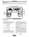
3.1 ROBOT CONTROLLER ELECTRICAL
CHARACTERISTICS
The following signals are referenced to the robot con-
troller’s 24V supply unless otherwise noted. The total
allowable load on the 24V supply is 0.7A.
The following is a brief description of the electrical
characteristics, for a full description see the Fanuc
electrical connections manual.
3.1.1 DIGITAL OUTPUTS
Rated Voltage: 24VDC
Maximum Applied Voltage: 30VDC
Maximum Load Current: 0.2A
Transistor Type: Open collec-
tor NPN
3.1.2 DIGITAL INPUTS
Maximum Input Voltage: 28VDC
High Input Voltage: 20 to 28VDC
Low Input Voltage: 0 to 4VDC
Input Impedance: 3.3K Ohms
Response Time: 5 to 20mS
3.1.3 ANALOG OUTPUTS
Weld equipment analog outputs are isolated
from the robot controller 24V supply.
Maximum Output Range: 0 to 10V
Load Impedance: 3.3K Ohms
or more
3.1.4 ANALOG INPUTS
Maximum Input Range: 0 to 10V
3.1.5 WIRE STICK DETECT
The wire stick detect output is isolated from the
robot controller 24V supply.
Maximum Output Voltage: 15VDC
Maximum Output Current: 85mA
4. POWER WAVE CIRCUITS
4.1 VOLTAGE COMMAND
The voltage command from the robot controller
(DACH1) is directly connected to the TIG analog input
on the display board of the Power Wave. This signal is
not connected to the robot or control ground.
Maximum Input Range: 0 to 10V
Typical Zero Offset: 0.55 to 0.65V
Typical Range: 9.0V
Input Impedance: 200KΩ
4.2 WIRE FEED SPEED COMMAND
The wire feed speed command from the robot con-
troller (DACH2) is directly connected to the WF1 ana-
log input on the display board of the Power Wave. This
signal is not connected to the robot or control ground.
Maximum Input Range: 0 to 10V
Typical Zero Offset: 0.55 to 0.65V
Typical Range: 9.0V
Input Impedance: 200KΩ
4.3 TOUCH SENSE SIGNAL
The touch sense signal is generated by active high
miscellaneous output #4 (bit #3) on the control board.
The signal is then isolated from the control ground,
inverted, and tied to the robot controller welding input 1
(WDI1). The active state table is responsible for set-
ROBOTIC INTERFACE
C-3 C-3
POWER WAVE 450
CAUTION