


ACCESSORIES
D-4 D-4
POWER WAVE 450
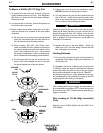
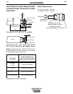
Standard 4-Roll Kits (KP655 and KP656)
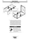
1) Turn off welding power source.
2) Release both quick release levers by sliding the
levers sideways into the open positions.
3)
Remove clamping screw & clamping collar from the
drive shaft closest to the incoming side of the feeder.
4) Install drive roll onto keyed shaft. (Do not exceed
the maximum wire size rating of the wire drive.)
Replace collar and tighten clamping screw.
5) Back out the set screw for the middle guide tube.
Install the middle guide tube and slide it up against
the drive roll. DO NOT TIGHTEN THE MIDDLE
GUIDE AT THIS TIME.
6) Install the outgoing drive roll following the same
procedure as steps 3 & 4.
7) Center the middle guide between the two drive rolls
and tighten in place.
8) Back out the screws for the incoming and outgoing
guide tubes.
9) Install the longer
guide tube in the rear hole near
the incoming drive roll. Slide the tube in until it
almost touches the roll. Tighten in place.
10) Install the remaining guide tube in the front hole.
Be certain that the proper plastic insert is used.
Fine wire chisel point tube m
ust have largest radius
next to drive roll. Tighten in place.
11) Re-latch both quick release levers.
12) To start new electrode, straighten the first 6”
(150mm) and cut off the first 1” (25mm). Insert free
end through the incoming tube. Press gun trigger
& push wire into the drive roll.
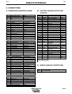
DRIVE ROLL AND GUIDE TUBE KITS:
Steel Wire Siz
es: 4-Roll
* .068 - 3/32” (1.7 - 2.4mm) Cored KP655-3/32
* 1/16” (1.6mm) Cored or Solid KP655-1/16
.045 - .052” (1.2 - 1.4mm) Solid KP655-052S
.045 - .052” (1.2 - 1.4mm) Cored KP655-052C
.035” (0.9-1.0mm) Cored KP655-035C
.035” (0.9-1.0mm) Solid KP655-035S
.030” (0.8mm) Solid KP655-030S
.023” (0.6mm) Solid KP655-025S
Aluminum Wire Sizes:
1/16” (1.6mm) KP656-1/16A
KP647-1/16A**
3/64” (1.2mm) KP656-3/64A
KP647-3/64A**
.040” (1.0mm) KP647-040A**
.035” (0.9mm) KP656-035A
Drive rolls for only cored electrode sizes are stencilled with a “C” suf-
fix to the wire sizes.
Drive rolls for only solid
electrode sizes are stencilled with an “S” suf-
fix to the wire sizes.
Drive rolls for aluminum wire sizes are stencilled with an “A” suffix to
the wire sizes.
* Not for Synergic 7FH model.
** For use with Binzel European guns. Installation instructions are
included with these kits. Also requires K489-2 Fast-Mate Adapter.
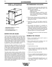
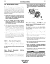
PROCEDURE TO INSTALL DRIVE
ROLL AND GUIDE TUBES
ELECTRIC SHOCK can kill.
• Do not touch electrically live parts such
as output terminals or internal wiring.
• When inching with gun trigger, electrode
and drive mechanism are “hot” to work
and ground.
• Turn OFF welding power source before
installing or changing drive roll and/or
guide tubes.
• Welding power source must be connected
to system ground per the National
Electrical Code or any applicable local
codes.
• Only qualified personnel should
perform this installation.
WARNING
Observe all additional Safety Guidelines detailed
throughout this manual.