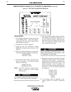
PROCEDURE
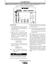
1. The voltage calibration numbers are stored
in the display board. They are program-
mable from the front panel using the Test
and Calibration Overlay.
2. Change the PC board in question.
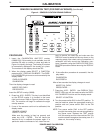
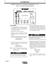
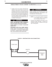
3. Install the Test and Calibration Overlay
L9660-255 and power up the machine. See
Figure 6.
4. Press the Voltage Calibration function (32).
The machine should display the following:
VOLTAGE WIRE
+ POLARITY (+67A)
5. Press the Enter Key (133) on the lower right
side of the overlay. The machine should
display the following:
ADJUST TO 30V
CALIBRATION #=XX
NOTE: Here “XX” indicates a particular cali-
bration number for a given voltage
sensing point.
The machine’s output terminals will be electri-
cally “HOT” when the Enter Key is pressed.
6. With the machine loaded, monitor the refer-
ence voltage only (external voltmeter). It is
the only important reading. Adjust the volt-
age using the Arrow Keys (100 and 101)
until the reference voltmeter reads 30.0
volts. Press the Enter Key.
WHEN LOADING THE MACHINE WITH THE
CASE PARTS REMOVED, BE CAREFUL NOT
TO OVERHEAT THE MACHINE.
7. Repeat the process by pressing the Voltage
Calibration function again. The next volt-
age sensing point (lead) may be selected by
pressing the down Arrow Key (101). The
above procedure must be repeated six
times to set the six sensing points (leads) to
30.0 volts. The six test points (leads) are
the following:
+ Polarity (+67A)
- Polarity (+21A)
+ Polarity (+67B)
- Polarity (+21B)
+ Polarity
- Polarity
8. If the display board is replaced or dis-
turbed, perform the Sensor Calibration
Test.
CAUTION
WARNING
16 16
SEMIAUTOMATIC PW450 FULL VOLTAGE CALIBRATION(continued)
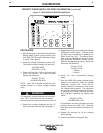
Figure 6 - TEST AND CALIBRATION OVERLAY
(32)
(34)
(36)
(64)
(33)
(35)
(37)
(65)
(67)
(96)
(97)
(98)
(99)
(100)
(101) (132)
(133)
(128)
(130)
(129)
(131)
CALIBRATION
POWER WAVE CALIBRATION


