


TEST PROCEDURE AFTER REPAIR
31 31
POWER WAVE CALIBRATION
The following five steps should be completed after examining and or repairing a Power Wave 450R. These steps
will insure that all aspects and systems of the Power Wave are functioning. This procedure does not include fan
operation, or proper water cooler operation, both of which are industry standard systems not requiring specific
technical interpretation. It is assumed that the repair technician is familiar with the basic functions of the Power
Wave and how to determine that the machine is powering up correctly and understands the overlay system and
memory operations. Additionally, those systems, if not functioning properly, should be clearly apparent to the tech-
nician.
After completing repairs, and or cleaning the unit, and while bearing in mind and following all safety precautions
listed in the service manual, proceed as follows.
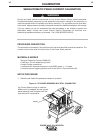
1. Check to insure the 5 Amp circuit breaker on the lower front of the machine does not trip when the machine is
on. A tripping breaker indicates a faulty I full wave bridge rectifier mounted on the left side of the control box, or
a defective Interface printed circuit board
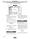
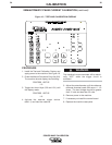
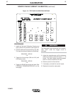
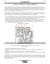
2. Remove the cover to the control box, look at the component side of the Interface board, and with the power on,
observe a flashing LED on the Interface board. If LED is not flashing, replace Interface board.
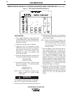
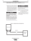
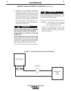
3. Disconnect the power, and measure the resistance from:
P83 feeder connector pin F to J103 pin 6 at the Interface board connector.
P83 feeder connector pin G to J103 pin 5 at the Interface board connector.
P83 feeder connector pin H to J103 pin 7 at the Interface board connector.
Each resistance check should yield a maximum resistance of 6.5 ohms, with no continuity between any two indi-
vidual F, G or H pins.
If a high resistance on one lead is found or two leads shorting together, locate the T12218-7 inductors soldered
into the harness you are checking and replace or repair the condition. Recheck.
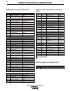
4. Complete the voltage, current, and Interface board calibration. The calibration procedures are provided in the
IM 573 and additional up-dated information appears the latest service CD.
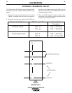
5. Replace covers on the machine, and attempt to trigger the unit following the procedure listed in the EXTERNAL
TRIGGERING CIRCUIT procedure in the Power Wave PC Board Replacement Calibration Procedures, IM 573.
Pay close attention to the polarity of the 24V. DC. Incorrect polarity will result in damage to the Interface board,
Verify O.C.V.
These steps, along with the expected contactor closure and display information will insure that all circuits of the
Power Wave 450 are operational.