


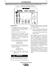
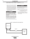
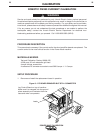
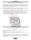


The Power Wave 450 Robotic may be triggered inde-
pendent of the robot using the following circuit and pro-
cedure.
1. Remove the large connector plug on the rear of the
PW450. (As viewed from the front of the machine).
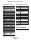
2. Connect a normally open switch and a 24VDC sup-
ply either to the large connector plug (P82) or to the
harness connectors on the interface board. See the
following table and figure.
3. When the 24VDC supply is correctly wired in place
and turned on the welding output terminals can be
energized by closing the switch.
CALIBRATION
28 28
POWER WAVE CALIBRATION
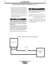
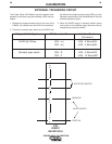
EXTERNAL TRIGGERING CIRCUIT
Voltage / Switch Signal P82 Connector Pins Interface Board
Connectors
24VDC @ 100ma P82 - r(+) J106 - 3 Wire #534
P82 - a(-) J106 - 4 Wire #535
Normally open switch P82 - R J105 - 4 Wire #518
P82 - P J105 - 12 Wire #527
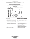
A
B
P
R
S
Z
a
b
c
m
n
p
r
s
P82
ROBOT
RECEPTACLE
ARC START SWITCH
NEGATIVE
POSITIVE
24VDC SUPPLY