


A-5
INSTALLATION
SAE400 WELD’N AIR
A-5
WELDING OUTPUT CABLES
With the engine off, connect the electrode and work
cables to the studs provided. These connections
should be checked periodically and tightened if neces-
sary.
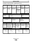
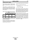
Listed in Table A.1 are copper cable sizes recom-
mended for the rated current and duty cycle. Lengths
stipulated are the distance from the welder to work and
back to the welder again. Cable sizes are increased for
greater lengths primarily for the purpose of minimizing
cable voltage drop.
Table A.1 Combined Length of Electrode and Work
Cables.
MACHINE GROUNDING
Because this portable engine driven welder creates its
own power, it is not necessary to connect its frame to
an earth ground, unless the machine is connected to
premises wiring (home, shop, etc.).
To prevent dangerous electric shock, other equipment
powered by this engine driven welder must:
a) be grounded to the frame of the welder using a
grounded type plug,
or
b) be double insulated.
When this welder is mounted on a truck or trailer, its
frame must be securely connected to the metal frame
of the vehicle. When this engine driven welder is con-
nected to premises wiring such as that in a home or
shop, its frame must be connected to the system earth
ground. See the article on grounding in the latest U.S.
National Electrical Code and the local code.
In general, if the machine is to be grounded, it should
be connected with a #8 or larger copper wire to a solid
earth ground such as a metal water pipe going into the
ground for at least ten feet and having no insulated
joints, or to the metal framework of a building which
has been effectively grounded. The U.S. National
Electrical Code lists a number of alternate means of
grounding electrical equipment. A machine grounding
stud marked with the symbol is provided on the
welding generator frame foot.
Up to 100
FT.
2/0 AWG
100-200 FT.
3/0 AWG
200-250 FT.
4/0 AWG
AMPS
@60%
Duty Cycle
400
TOTAL COMBINED LENGTH OF ELEC-
TRODE AND WORK CABLES