


B-2
OPERATION
B-2
The user adjusts WFS according to factors such as
weld size, penetration requirements, heat input, etc.
The power source then uses the WFS setting to adjust
its output characteristics (output voltage, output cur-
rent) according to pre-programmed settings contained
in the power source. In constant current modes (arc
gouging, stick, TIG) this control adjusts the output cur-
rent, in amps. An LED lights to inform the user which
function (WFS or amps) is active.This display can be
either English or metric units. Further, this display can
be set up to display either WFS or amps when using
wire welding modes. (See SETTING DIP SWITCHES
in the INSTALLATION section.)
The right knob is labeled VOLTS / TRIM. In constant
voltage modes (synergic CV, standard CV) the control
adjusts the welding voltage. In pulse synergic welding
modes (pulse GMAW only) the user can change the
Trim setting to adjust the arc length. It is adjustable
from 0.50 to 1.50. A Trim setting of 1.00 means than
no adjustments will be made to the preset arc lengths,
and is optimum for most conditions. An LED lights to
inform the user which function (volts or trim) is active.
Both displays indicate preset values, according to the
weld mode selected, when not welding. Once weld-
ing begins, they switch to displaying actual values. At
that time, the indicator LEDs will flash to signify actual
values are being displayed. The displays hold the
actual values for 5 seconds after a weld is stopped.
Turning a knob during the hold time shuts off the hold,
and returns the meters to their preset values.
The allowable settings are determined by other sys-
tem components. The WFS range, for instance, is
dependent upon the gear range in the Wire Drive and
on the welding programs in the Power Wave power
source. The voltage and current are similarly limited
by programs in the Power Wave.
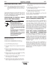
CONTROL BOX PANELS - “SMALL” OPTIONAL PANELS
K1542-5 Dual Procedure Panel:
This panel provides for setting and manual selection
of two procedures with a toggle switch. Selection can
be done at the panel, or through a dual procedure
welding gun switch connected to the Wire Drive trig-
ger receptacle. The upper position selects Procedure
A, while the lower selects Procedure B. The middle
position selects the Gun Switch, in which case the
procedure is determined by the dual procedure weld-
ing gun switch. Note: When in the Gun Switch
mode, this option does not have provisions for indicat-
ing which remotely selected procedure (A or B) is
active.
To set Procedure A, move the switch to the A position.
Make all desired settings on the Control Box. Settings
are automatically saved as changes are made. Do
the same for procedure B. If using a gun switch to
select procedures, set the switch to Gun Switch.
Procedure A is the default if no gun switch is present.
Settings are saved at power down.
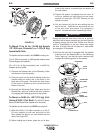
K1542-9 Dual Procedure / Memory Panel:
This panel provides two functions: Dual Procedure
and Memory. Dual Procedure provides for setting and
manual selection of two procedures. Selection can be
done at the panel, or through a dual procedure weld-
ing gun switch connected to the Wire Drive trigger
receptacle. Memory provides six independent storage
locations for Control Box settings. All selections are
done with push buttons and indicator lights. Dual
Procedure can be used without making use of
Memories; the opposite is also true.
To set Procedure A, hit the Procedure button until the
A LED illuminates. Make all desired settings on the
Control Box. Settings are automatically saved as
changes are made. Do the same for procedure B. If
using a gun switch to select procedures, hit the
Procedure button until the Gun LED illuminates.
When in the Gun mode is selected, either light A or B
will be flashing. The flashing light identifies the
Procedure, A or B, which is selected by a dual proce-
dure gun switch. If no dual procedure switch is
plugged in, the Procedure defaults to A. Settings are
saved at power down.
To load a memory, start by setting all adjustments and
functions on the Power Feed to the desired settings.
To save the settings to Memory 1, simply hit the Save
button (its red light will illuminate) and then hit the 1
button. The settings are now saved in Memory 1. The
contents of Memory 1 will not change, even if the
power is turned off, until the next time the Save key
and the 1 key are hit in sequence. The same proce-
dure can be applied to each of the other 5 memories.
If the Save key is hit accidentally, simply hit the Save
button again, its light will go out, and the Save func-
tion will be canceled.
Note: It is not required to load all 6 memories at once,
nor is it necessary to load them in order. Memory can
be loaded at any time, except when welding.
Similarly, the Save key is not active while the gun trig-
ger is pulled, or while welding.
POWER FEED 10