


E-12
TROUBLESHOOTING
E-12
POWER FEED 10
If for any reason you do not understand the test procedures or are unable to perform the tests/repairs safely, contact your
Local Lincoln Authorized Field Service Facility for technical troubleshooting assistance before you proceed.
CAUTION
Observe all Safety Guidelines detailed throughout this manual
Note:
For any Err # listed below write down the error number for reference and try cycling power to see if the
error clears itself. If not, refer to the What to Do column for the given Err.
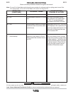
PROBLEMS
(SYMPTOMS)
POSSIBLE CAUSE
RECOMMENDED
COURSE OF ACTION
Display shows any of the following:
Err 211
Err 212
- - - (three dashes)
Microprocessor RAM error in Control
Box.
Microprocessor RAM Error in object
board other than Control Box (Such
as feed head).
Appears on right display of Circuit
Board module that contains the sta-
tus LED.
Turn Power off at power source.
Wait 5 seconds. Turn power back
on. If Err 211 is displayed again,
then replace CB mother PC board.
Cycle power as in Err 211. If Err 212
is still displayed, then replace the PC
board in the object with the fault. The
object with the fault should be solid
red on its status LED.
This is an indication that a constant
current such as stick or gauge mode
has been selected. Turning the right
encoder clockwise when in this state
will activate output to Power Source.
Turning the right encoder counter-
clockwise will deactivate output.