


A-4
INSTALLATION
A-4
SAE400 & SAE400 WELD’N AIR
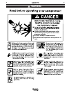
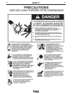
• Stop engine while fueling.
• Do not smoke when fueling.
• Keep sparks and flame away from
tank.
• Do not leave unattended while
fueling.
• Wipe up spilled fuel and allow
fumes to clear before starting
engine.
• Do not overfill tank, fuel
expansion may cause over-
flow.
DIESEL FUEL ONLY
------------------------------------------------------------------------
Fill the fuel tank with clean, fresh diesel fuel. The capac-
ity of the fuel tank is 22.5 gallons (85.1 liters). See engine
Operator’s Manual for specific fuel recommendations.
NOTE:
Before starting the engine, be sure the fuel shut-
off valve on the sediment bowl is open by turning the han-
dle counterclockwise.
ENGINE COOLING SYSTEM
The cooling system has been filled at the factory with
a 50-50 mixture of ethylene glycol antifreeze and
water. Check the radiator level and add a 50-50 solu-
tion as needed. (See Engine Manual or antifreeze
container for alternate antifreeze recommendation.)
ENGINE BREAK-IN PERIOD
Lincoln Electric selects high quality, heavy-duty indus-
trial engines for the portable welding machines we
offer. While it is normal to see a small amount of
crankcase oil consumption during initial operation,
excessive oil use, wetstacking (oil or tar like substance
at the exhaust port), or excessive smoke is not normal.
Larger machines with a capacity of 350 amperes and
higher, which are operated at low or no-load conditions
for extended periods of time are especially susceptible
to the conditions described above. To accomplish suc-
cessful engine break-in, most diesel-powered equip-
ment needs only to be run at a reasonably heavy load
within the rating of the welder for some period of time
during the engine’s early life. However, if the welder is
subjected to extensive light loading, occasional moder-
ate to heavy loading of the engine may sometimes be
necessary. Caution must be observed in correctly
loading a diesel/generator unit.
1. Connect the welder output studs to a suitable resis-
tive load bank. Note that any attempt to short the
output studs by connecting the welding leads
together, direct shorting of the output studs, or con-
necting the output leads to a length of steel will
result in catastrophic damage to the generator and
voids the warranty.
2. Set the welder controls for an output current and
voltage within the welder rating and duty cycle.
Note that any attempt to exceed the welder rating or
duty cycle for any period of time will result in cata-
strophic damage to the generator and voids the
warranty.
3. Periodically shut off the engine and check the
crankcase oil level.
BATTERY CONNECTION
Use caution as the electrolyte is a strong acid that
can burn skin and damage eyes.
Remove and discard the insulating caps from the
negative battery terminals. Attach and tighten neg-
ative battery cable terminals.
NOTE:
This machine is furnished with wet charged
batteries; if unused for several months, the batteries
may require a booster charge. Be careful to charge the
batteries with the correct polarity. Make sure that the
batteries are level while charging.
GASES FROM BATTERY can
explode.
● Keep sparks, flame and cigarettes
away from battery.
-----------------------------------------------------------------------
To prevent EXPLOSION when:
● INSTALLING A NEW BATTERY — disconnect
negative cable from old battery first and
connect to new battery last.
● CONNECTING A BATTERY CHARGER —
remove battery from welder by disconnecting
negative cable first, then positive cable and
battery clamp. When reinstalling, connect
negative cable last. Keep well ventilated.
● USING A BOOSTER — connect positive lead to
battery first then connect negative lead to neg-
ative battery lead at the lower control panel
support.
DIESEL FUEL
can cause fire.
WARNING
WARNING
WARNING