


F-1
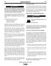
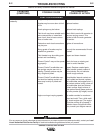
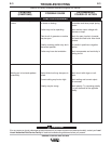
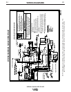
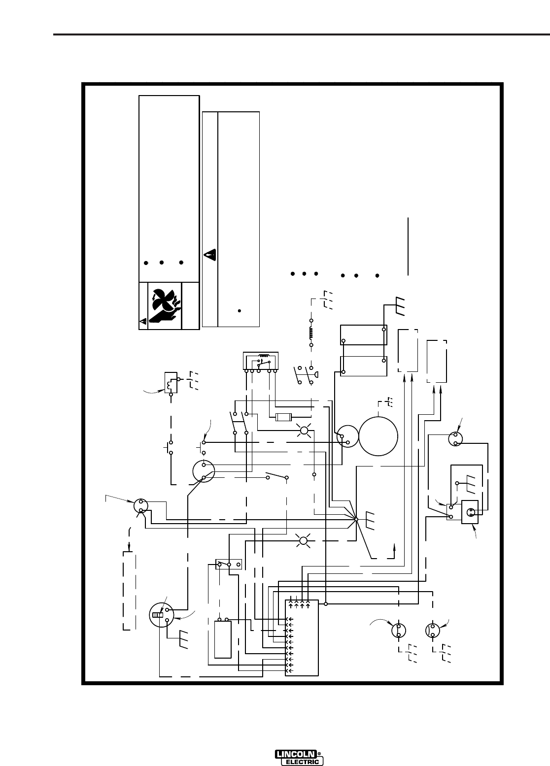
WIRING DIAGRAMS
SAE400 & SAE400 WELD’N AIR
F-1
B
239
Enable
TERMINAL
Compressor
IGNITER
COLD
B
233
THERMOSTART
B
B
-
START
THERMOSTART
230
W
30
B
B
229
B
234
220
B
B
IDLER
SWITCH
IND
J2
PROTECTION
P.C. BOARD
IDLER/ENGINE
J1
+
TO TOROID
2 CR
REED RELAY
R
GROUND SCREW
B
STARTING
Pressure SW.
TO CONTROL PANEL
B
232
G
243
B
SWITCH
240
B
-
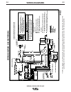
WIRING DIAGRAM - SAE-400 WELD'N AIR
236
226
U
231
222
U
S
G
B
228
G
W
R
241
242
B
B
B
R
4
238
G
W
TO FLASHING DIODE
ENGINE HOUR METER
2
3
3
G
B
B
221
G
IGNITION
9
8
5A
7
6
5B
5
1
86
85
87
87a
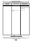
AS REQUIRED:
DAILY CHECKS:
-
Clutch
Compressor
B
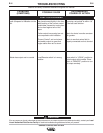
LEAD COLOR CODE
G
-
FUEL INJECTION PUMP
FUEL SHUT
+
TEMPERATURE GAGE
MOTOR
ENGINE TEMP.
SENSOR
B
1
10
G
4
OFF VALVE
+
SWITCH (N.C.)
OIL PRESSURE
+
+
M19232
5C
G
W
R
237
2
ALTERNATOR
SOLENOID
IDLER
GENERAL MAINTENANCE INSTRUCTIONS FOR ENGINE
AND MOTOR DRIVEN ARC WELDING POWER SOURCES.
11-
01
MAINTENANCE INSTRUCTIONS
B
Y
AMMETER
B
Fuse
(10A)
B-BLACK OR GRAY
G-GREEN
N-BROWN
R-RED OR PINK
U-BLUE
W-WHITE
Y-YELLOW
B
235
PARTS
CAN INJURE
MOVING
maintenance work.
maintenance work unless the maintenance work
Keep hands, hair, clothing and tools away
requires it to be running.
Turn the engine or input power OFF before
Have only qualified personnel perform
WARNING:
from moving parts, and insure all guards or
covers are replaced after servicing.
Engine oil, coolant, air cleaner and fuel
All equipment in serviceable condition.
Welding cable connections are tight.
strainer are at proper operating level and clean.
Blow dust from machine using clean low pressure air.
Clean commutators or slip rings with fine sandpaper-
NOT EMERY CLOTH. See Operating Manual for instructions.
Replace brushes before the pigtails are within 1/4"of
the commutator. See Operating Manual for instructions.
WARNING
Uncontrolled release of door restraint cords can cause injury.
Keep secure hold of cord, and keep face away
from cord when hooking or releasing hook.
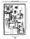
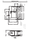
NOTE: This diagram is for reference only. It may not be accurate for all machines covered by this manual. The
specific diagram for a particular code is pasted inside the machine on one of the enclosure panels.