


A-8
INSTALLATION
COMMANDER 300
A-8
CONNECTION OF LINCOLN
ELECTRIC WIRE FEEDERS
ELECTRIC SHOCK can kill.
Shut off welder before making any
electrical connections.
------------------------------------------------------------------------
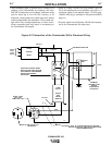
CONNECTION OF THE LN-25 TO THE
COMMANDER 300
The LN-25 with or without an external contactor may
be used with the Commander 300. See the appropriate
connection diagram in the DIAGRAMS section.
NOTE: The LN-25 (K431) Remote Control Module and
(K432) Remote Cable are not recommended for use
with the Commander 300.
• Shut the welder off.
• For electrode Positive, connect the electrode cable
from the LN-25 to the “+” terminal of the welder and
work cable to the “-” terminal of the welder. For elec-
trode Negative, connect the electrode cable from the
LN-25 to the “-” terminal of the welder and work
cable to the “+” terminal of the welder.
• Attach the single lead from the front of the LN-25 to
work using the spring clip at the end of the lead. This
is a sense lead to supply current to the wire feeder
motor; it does not carry welding current.
• Set the SELECTOR switch to the “CV-WIRE” posi-
tion.
• Set the “WELDING TERMINALS” switch to “WELD
TERMINALS ON”
• Adjust the “ARC CONTROL” knob to desired crisp-
ness. Generally, welding is best if the “ARC CON-
TROL” is set to SOFT for MIG and CRISP for
Innershield. You may however, want to start in the
middle and adjust (as needed) from there.
• Set the “IDLE” switch to the “AUTO” position. When
not welding, the Commander 300 engine will be at
the low idle speed. If you are using an LN-25 with an
internal contactor, the electrode is not energized until
the gun trigger is closed.
ELECTRIC SHOCK can kill.
If you are using an LN-25 without an
internal contactor, the electrode will be
energized when the Commander 300 is started.
------------------------------------------------------------------------
h. When the gun trigger is closed, the current sensing
circuit will cause the Commander 300 engine to go
to the high idle speed, the wire will begin to feed
and the welding process started. When welding is
stopped, the engine will revert to low idle speed
after approximately 12 seconds unless welding is
resumed.
CONNECTION OF LN-7 OR LN-8 TO THE
COMMANDER 300
• Shut the welder off.
• Connect the LN-7 or LN-8 per instructions on the
appropriate connection diagram in the DIAGRAMS
section.
• Set the “WIRE FEEDER VOLTMETER” switch to
either “+” or “-” as required by the electrode being
used.
• Set the “SELECTOR” switch to the “CV-WIRE” posi-
tion.
• Adjust the “ARC CONTROL” knob to desired
Crispness. SOFT for MIG and CRISP for Innershield.
• Set the “WELDING TERMINALS” switch to the
“REMOTELY CONTROLLED” position.
• Set the “IDLE” switch to the “HIGH” position. When
not welding, the Commander 300 engine will be at
the low idle speed.
WARNING
CAUTION